

10 October 2009
I discovered a flaw in the current design that will only allow the controller to work with a connection to the computer and not to a microcontroller. I've updated the schematic below and will fix the controller design. I've added a project file below that also includes the fixed schematic.
If you look at the schematic you will notice that when you set the jumper to non-inverted so you can connect to a microcontroller for serial control it will not work. The reason is in the way I designed the circuit for both inverted/non-inverted RS232 control. Looking at the transistor in the circuit, the collector is held high through a 10K resistor. The collector feeds to the Rx pin on the PIC. When you set the jumper to non-inverted and attempt to send data to the PIC it won't work because the line is always tied high through R8 to 5V.
There is a fix and I have included it in the archive file below. There are two ways to do this:
1. If your board is already built and your intentions are to only use this LCD in a finished design and not attached to the computer then, snip the connection from R8 to 5V and the controller will only work in the non-inverted configuration.
2. Look at the included schematic in the archive and add the shown J2 jumper to your design which will allow you to select between the two types of communication.
04 October 2009
I have redesigned the LCD Controller and updated the code. The new schematics and code can be found below. I ported the code from MBasic to PicBasic Pro. I'll leave the old code up for those who still want it.
The files below are from a project that I have been working on for a serial LCD controller for a 4x20 line parallel display with the Hitachi chipset. I am also working on a USB design. In the picture of the demo board there is a wire jumper installed. This is because I screwed the pooch and somehow missed a crossed trace. I had to repair the board. In the download files the PCB files have been fixed. I'll upload some video of functionality when I get a chance.
The code and project files have been posted in the download links.
Project file downloads
Old code:
Power regulation board schematic
Demo application with sourcecode
05 October 2009 Project Files
PicBasic Pro PIC16F628A code for 16x2 character LCD
PicBasic Pro PIC16F628 code for 16x2 character LCD
PicBasic Pro PIC16F628A code for 20x4 character LCD
Archive containing test application, schematic, and PCB (ExpressPCB)
PicBasic Pro LCD Controller interface to Parallax GPS receiver
Ensure all the files are unzipped to the same folder. The include file that is referenced contains the fuse settings for the selected PIC chip.
I will be uploading a version soon that allows the type of LCD to be set. This will allow the same controller to be used for a variety of LCDs. I can't squeeze that functionality into a PIC16F628 chip without removing some of the current functionality. So, I am porting that over to a PIC16F88.
More to come...
Breadboard testing of the LCD controller

Software application for testing functionality

LCD controller schematic

A better view of the controller schematic can be downloaded from the link below:
http://picasaweb.google.com/lh/photo/LZac_OpDpd0lbB8jCWJL0Q
USB version of the LCD controller

A better view of the controller schematic can be downloaded from the link below:
http://picasaweb.google.com/lh/photo/_XtaXjprlNdzRaFHGrha_Q
Optional power supply schematic

A better view of the controller schematic can be downloaded from the link below:
http://picasaweb.google.com/lh/photo/Hp0EJqKk4PNbVm69Vd1p8g
Component layout

PCB with two controllers and the optional power supply

PCB bottom side

PCB top side

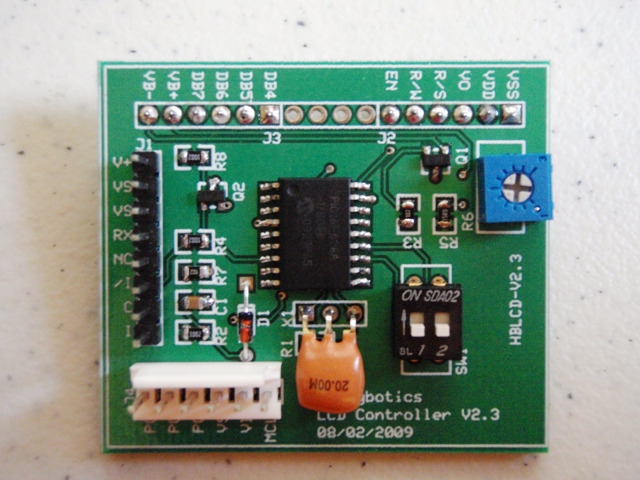
LCD prototype board component view

Prototype board attached to the back of a LCD

Netlist
Serial LCD Controller v1.4
----------------------------
C1 0.1uf
D1 1N4148
J1 16-pin Header
J2 4-pin Header, Right Angle
J3 3-pin Header
J4 6-pin Header. Right Angle
JP1 Shorting Jumper
Q1 2N2222
Q2 2N2222
R1 1M
R2 10k
R3 1k
R4 22k
R5 15
R6 10k Potentiometer
R7 1k
R8 10k
U1 PIC16F628
X1 20Mhz
HD44780 20x4 LCD Module Display
Netlist
USB BUS Powered LCD Controller
-------------------------------
C1 0.1uF
C2 10nF
C3 10uF
C4 0.1uF
C5 0.1uf
D1 1N4148
F1 500mA, Ferrite Bead
J1 USB Type B, Digikey 787780-1-ND
J2 ICSP, 6-Pin, Right Angle Header
J3 LCD Connector, 16-Pin Header
J5 2-Pin Header
J6 2-Pin Header
JP2 Shorting Jumper
JP3 Shorting Jumper
LED1 RED
LED2 GREEN
Q1 2N2222
R1 330
R2 330
R3 1M
R4 10k
R5 15
R6 1k
R7 10k
SW1 Power, SPDT
U1 FT232RL
U2 PIC16F628
X1 20Mhz
NOTE All resistors on the controller board are 1/8 watt
Netlist
5V Power Regulation v1.0
-------------------------
C1 10uf
C2 0.1uf
C3 10uf
D1 1N4004
D3 1N4004
J1 Power Jack
J2 3-pin header
LED1 Light Emitting Diode
R1 220
SW1 SPDT Slide Switch
VR1 LM7805
NOTE All resistors on the power board are 1/4 watt
You can do a search on eBay for the LCDs and you will find them listed for as cheap as $5.00 minus shipping.
04 October 2009 - Redesigned Controller
I have redesigned the controller to use some surface mount components. This is still a prototype and the final version will have all surface mount components and be a bit smaller. I also ported the code from MBasic to PicBasic Pro. MBasic is a great program but the makers have not updated it to include newer PICs. As such, I’ve been using PicBasic Pro which is a really nice basic compiler. The code size and speed rivals that of some PIC-C compilers.
Schematic
Newest Schematic with fix for connection to PC or microcontroller

Better view of the schematic can be downloaded at the following link: http://picasaweb.google.com/lh/photo/0gbrdTCrjH6KJyib-i33EQ?feat=directlink
Old schematic with flaw. Recommend not to build from this schematic

Better view of the schematic can be downloaded at the following link: http://picasaweb.google.com/lh/photo/Yi30Oi9tf_1AIOc2Z4cDGw?feat=directlink

Better view of the schematic can be downloaded at the following link: http://picasaweb.google.com/lh/photo/ySbtGz3Fb4xDZ26780GD8w?feat=directlink


Netlist:
| Hobbybotics LCD Controller V2.3 | ||||
| Component | Description | Part Number | Vendor | Cost |
| C1 | 0.1uf, SMT 0805 | 80-C0805C104M5R | Mouser | $0.05 |
| D1 | 1N4148, D0-35 | 512-1N4148T26A | Mouser | $0.03 |
| J1 | 8-Pin Straight Header, Male | 855-M20-9730846 | Mouser | $0.20 |
| J2 | 6-Pin Receptacle, Female | 649-68685-306LF | Mouser | $1.75 |
| J3 | 6-Pin Receptacle, Female | 649-68685-306LF | Mouser | $1.75 |
| J4 | 6-Pin Polarized Header | 571-6404546 | Mouser | $0.27 |
| JP1 | 2-Pin Jumper | 855-M22-1920005 | Mouser | $0.25 |
| Q1 | 2N2222, SOT-23 | 512-MMBT2222AD87Z | Mouser | $0.06 |
| Q2 | 2N2222, SOT-23 | 512-MMBT2222AD87Z | Mouser | $0.06 |
| R1 | 1M, 0805, 1/8W | 71-CRCW0805J-1M-E3 | Mouser | $0.07 |
| R2 | 10k, 0805, 1/8W | 71-CRCW0805-10K-E3 | Mouser | $0.05 |
| R3 | 1k, 0805, 1/8W | 660-RK73B2ATTDD102J | Mouser | $0.06 |
| R4 | 22k, 0805, 1/8W | 71-CRCW0805-22K-E3 | Mouser | $0.05 |
| R5 | 15, 0805, 1/8W | 71-CRCW0805-15-E3 | Mouser | $0.05 |
| R6 | 10k, Potentiometer | 72-T70YE-10K | Mouser | $0.74 |
| R7 | 1k, 0805, 1/8W | 660-RK73B2ATTDD102J | Mouser | $0.06 |
| R8 | 10k, 0805, 1/8W | 71-CRCW0805-10K-E3 | Mouser | $0.05 |
| SW1 | DIP-2 Switch | 611-SDA02H1BD | Mouser | $0.56 |
| U1 | PIC16F628A, SOIC-18 | 579-PIC16F628A-I/SO | Mouser | $2.14 |
| X1 | 20Mhz Resonator | 815-AWCR-20.00MD | Mouser | $0.32 |
| HD44780 20X4 LCD | RT204-1 | Ebay | $10.80 | |
| PCB | Printed Circuit Board | HBLCD-V2.2 | ExpressPCB | $14.14 |
|
|
|
|
|
Total |
|
|
|
|
|
$33.51 |

