Send commands from UART to RS232 using Arduino shield?

Hello!

I recently purchased the RS232 adapter for my Arduino Uno (robotshop.com/en/rs232-shield-arduino.html). It says that this shield converts UART into serial code.

I attached the shield to my arduino, and plugged in a DB9-to-RS232 cable. The RS232 end is connected to a liquid dispenser. The liquid dispenser requires the command “D” to be received via serial port in order to execute the desired function. I tried writing serial output into my arduino code, using the hexadecimal version of the ASCII code for the necessary characters. This is the relevant excerpt from my code:

Serial.write(0x44); //D
Serial.write(0x3C); //<
Serial.write(0x0A); //LF
Serial.write(0x3E); //>

However, this has no effect on the liquid dispenser, so obviously the command is not being communicated properly. Any advice?!

Thanks in advance.

-Kate

Hi Kate,

You most likely simply need to send 0x44, 0x0A, as probably stands for \n or 0x0A ASCII character, without the “<” and “>”.

Sincerely,

Hi,

Yes, this is probably true about eliminating the “<” and “>” characters, thanks! But when I tried that, still no response from the instrument. Just to clarify, the instrument that that the shield is connected to uses a DB25 so the cable is DB9-to-DB25. The tutorial for the shield indicates a DB9-to-USB should be used so I’m not sure if that’s the only cable that would work?

Do I need to make a connection with a wire between the “TxD” (pin 1) on the shield and the “RS232 RXD” pin on the shield for the signal to be communicated?

Thank you for your input!!

Kate

Hi Kate,

The shield requires no modification to work and is electrically connecting the hardware serial part (on a Arduino Uno, that is pins 0/1) to the DB9 port.

The device you are using may require other pins to be controlled that the shield is not doing (or your cable adapter, or both). To provide more advice, we need more information, such as:

]a link to the instrument you are using, datasheet, etc./:m]
]an attachment with the code you are using to connect to/control it/:m]
]pictures of your setup, showing clearly all componennts/:m]

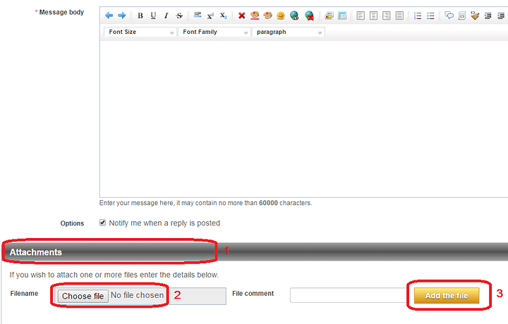
You can attach pictures and other files to your reply using the Full editor mode (see attached image for details).

Sincerely,

Hi Sebastien,

Thanks so much for getting back to me.

I have attached the relevant part of the instrument manual (the whole manual was too long to upload as an attachment here).
I have also attached my Arduino code. Parts of it are not relevant as they are used for motor control. The part pertaining to the serial output is in the loop section at the bottom.

I can go take pictures of the setup if thats helpful. It’s just this RS232 shield on top of my Arduino Uno, then an additional AdaFruit motor shield on top of that, with a DB9 connected to the RS232 shield and fed over to the instrument via DB25 port.

Thanks!

Kate
Multidrop_SerialControl.pdf (273 KB)
StepperControl.ino (4 KB)

Hi Kate,

Thanks for the protocol document. Luckily, the RTS/DTR (hardware control/handshake) lines do not seem to be required. That is good to know since the shield you are using does not support those.

Serial.write() would be the proper command to use, but Serial.print/println can work too, depending on how you setup your string/buffer for sending the command.

Assuming that your DB25<->DB9 converter cable redirects the TX/RX line around properly (you may want to check that quickly with a multimeter, continuity test), there seems to be no obvious electrical/hardware/interface issues.

As for your code, here is a few notes:

The serial code used to send a command to the dispenser seems valid at first glance. Did you check to confirm the “if(counter < rows){” block is executed? You could add extra debug code there, such as blinking a LED or something similar for a second so you know it is executing. You mentioned previously there is no effect on the instrument when writing to its serial interface, but is there any motor action? Are the timings (calculated delays) OK?

The line “else if (counter == rows) {” may very well never execute, depending on if counter and rows match up properly. If counter is ever changed in a way where it skips the value of rows, it would continue until overflow. A good way to prevent this is using something like “if (counter >= rows) {”.
Since there are only two options in this case, you could simply use “else {” at the end instead of a “else if (…) {”, since if it is not “< rows”, then it has to do that other code instead.

Also, it seems you have code to increment your counter value by +1 or +2, but no code to reset it to 0. Is that on purpose?

Another important point, your lines “if (platesize = 96) {” and “else if (platesize = 384) {” are using “=” (assignment) instead of “==” (equality test). Because of this, the first “if” would assign a value of 96 to platesize, which would the evaluate to true (0 = false, anything else = true).

On a general note, you may want to either define your “rowTime” variable as a float (so it can store non-integer values, right now it is defined as a int), or you could keep it as an int (probably a long instead) and instead calculate everything in ms to begin with. ex:

rowTime = 0.016*(volume) + 2.400; would become

rowTime = 16*(volume) + 2400; This would allow for fast and easy use of the numbers and also prevent losing precision due to conversion from float/integers and from representation in RAM (pure integer math is exact, whereas float may not be in most cases). We strongly recommend using the integer (long) solution since it would make using delay() more straightforward, too, since that function only accepts unsigned long values and therefore another conversion is made there when you pass the value if it is not of the right time (ex: a float).

We recommend that you verify your code against all the comments above and see if that helps. It may be best to make a smaller example/test code where you only send one command once (ex: in setup()) to the device instead of in a loop, just as a test to see if it responds properly. Once you have working code to control that instrument, then integrate it into your loop.

Sincerely,

Hi Sebastien,

Thank you very much for your advice!

I purchased the cable to try to the tutorial and it worked just fine. So, clearly it is simply that my code isn’t communicating the commands properly, than a problem with the shield.

I took your advice in switching the “else is counter == rows” to a general “else” statement, and fixed the error in the “if” statements where I had a single = instead of ==.

Unfortunately, my code is still having no effect whatsoever on the instrument. I’ve tried communicating the characters in hex, in binary with Serial.write() commands for each character as well as a block of individual Serial.write() commands for each bit in each character, and nothing seems to work.

I notice in the sample code that a different pin is used, pin 13. If I try to make a Soft Serial instead of using the default hard serial pins 0 and 1 on the Uno, how would I specify that these pins outputs need to go to the RS232 Tx on the shield?

Any other advice would be much appreciated as I have hit a dead end as far as various formats that might get my commands across. Thanks so much for your help thus far.

Thanks,
Kate

Hi Kate,

Here are some answers to your questions and comments:

Do you mean this tutorial?

The only logical reason for this to happen would be that the switch is in the OFF position or it is placed to the ON position after the code already executed.

I assume you mean this example code? If so, please note pint 13 (on an Arduino Uno and many other compatible boards) is hardwired to a LED. This is unrelated to your hardware serial port.

You cannot use a different set of pins in this case since the TX & RX pins are hard-wired to the pins 0/1 of the Arduino (hardware serial port).

On a different note, did you switch the port switch to “ON” when using it? I know this sounds very basic, but it should be checked, too. To upload code to the Arduino when the shield is on, you need to switch the shield “OFF”. Then, once the code is uploaded, you need to place the switch back to “ON” for the shield to be connected to the Arduino and RS-232 cable. Afterwards, you will need to reset your Arduino so that it can run its code properly.

Also, since the USB cable is still connected to the Arduino (and therefore the hardware serial port), you should be able to monitor what is sent and received through the serial port with the Arduino Serial Monitor. Please open the Serial Monitor and see if your code actually sends the commands you expect through the serial port.

Let us know how all of this goes!

Sincerely,

Hi Sebasiten,

Thanks so much for the quick response.

That’s what I figured as far as using different pins. Thanks for confirming. I did mean that tutorial, both times I said it.

My method has been to upload the code via USB with the shield off, then disconnect the USB, switch on the shield, and then plug in the 9V supply, at which point the code executes.

Unfortunately I haven’t been able to leave both the USB and 9V source plugged in, as for some reason, my Arduino does not work at all when both sources are in. I need to power via the 9V because the motor being run requires high voltage. Any idea why it doesn’t work with both USB and power source plugged in? That might be a question for Arduino people instead.

The instrument is being powered separately, so I don’t imagine that I would need to be sending a higher voltage through the Arduino power source.

Thank you!

Kate

Hi Kate,

Since you are trying to troubleshoot the serial communication with the instrument (and not the motor control), I recommend that you remove the 9 V DC power source and the motor control temporarily.
This will allow you to test your serial setup in isolation, which will make it simpler.

With that done, you should be able to use only the Arduino, the RS-232 shield, the USB cable and the instrument. In such a setup, you should be able to use Serial Monitor for testing the outputs from your code. Without this info, we are working blind and have to assume your code is producing the proper output (it may not).

Sincerely,

Hi Sebastian,

That makes sense. I have noticed that, when monitoring via serial monitor, sending the commands in binary does NOT work properly but produces boxes rather than the characters. When I send the commands in hex it does produce the right characters.

However I’m not sure that I can send the command in hex because the instrument manual specifies that the character format must be: 1 start bit, 8 bits, 1 stop bit, no parity. Will the shield somehow convert my hex characters to this or do I need to write my code to just output in this format? The serial monitor clearly does not understand that format but I thought maybe the instrument would since it’s built to accept that format.

Thanks again,
Kate

Hi Kate,

It seems to me like your instrument expects ASCII (clear text) serial commands. Therefore, simply use Serial.print() / Serial.println(). Try to simply send Serial.print(“D\n”); and see what happens or something like Serial.print(“VER\n”);.

The 10 bit frame format (1 start bit, 8 data bits, (no parity bit), 1 stop bit) is the standard/typical format. This is taken care of by the Serial object on the Arduino side, actually. The shield only transfers the digital signals from the Arduino to a different interface, RS-232, which typically uses a differential ±12 V DC signal. The Arduino cannot product 12 V DC signals (or negative voltage) on its digital outputs, hence why the shield is needed.

Sincerely,

Hi again,

Great to know about the Arduino Serial object! That makes sense to just use the character and let it handle the conversion.

I’ve switched my setup to be powered via the USB so now can use the serial monitor, which confirms that the commands are being sent exactly as expected with proper timing, now using Serial.println().

Unfortunately the instrument is still unresponsive. Very strange. Anyhow, I really appreciate all of your time and advice and although I haven’t been successful (yet) I now understand what is going on far better, so thank you very much!!!

Best,
Kate

Hey Kate,

Glad we could help you out, if only with understanding your setup better. Let us know if you figure out what is happening exactly with the instrument.
At this point, you may want to simply contact the instrument’s manufacturer (or distributor) to see if they can offer more advice about what could be the issue.

Most of these companies tend to have a Contact Us page with specific forms for technical support (some even have live chat!), so that could help you quite a bit.

At least you now know that your setup is working as expected.

Sincerely,

Hey,

Just to wrap up this topic, I got the code working! For some bizarre reason that I’ll have to think through later, the gender changer seems to have been the issue?! I used a male-to-male gender changer as both my serial cable and the shield are female. This seems to have been the issue- I have manually wired shieldTx-cableRx, shieldRx-cableTx, and GNDs and now the communication works beautifully. With the very very simple code from the beginning, Serial.println(“V”); etc. the shield commands the instrument effectively.

Thanks so much for all of your help troubleshooting this.

Best,
Kate

Hi Kate,

I’m glad your situation is resolved. Hopefully, this has given new things to consider going forward!

Good luck with the project and we wish you a nice holiday period!

Sincerely,

I’m also having trouble with the RS232 Arduino Shield. I’m trying to connect it to an Ohaus Scale (SPX 621) but am not receiving data from the scale.

Do I need to use a null modem cable to connect to my device?

I’ve tried running the example code from the previously mentioned tutorial, but changing ‘V’ to CP, which I expected to create a constant print output from the scale.
I can’t attach the interface manual because I’m a new user, but it can be found here: https://us.ohaus.com/en-US/Products/Accessories/Other/Interface-Cables-and-Kits/RS232-Interface-Scout

So far I’ve had no luck in getting any data from the scale over the RS232 lines, any suggestions would be greatly appreciated!

To connect two RS-232 devices together, you will indeed need to match the RX of once side to the TX of the other. You can find wiring details here. Combine this information with what is found in the manual you linked to, page 7 (2.3 MB).
I strongly recommend to configure your device to use “none” for the hardware handshake. This will keep the wiring requires simple (TX, RX, GND).

These type of issues typically come down to three things:

  1. The physical connection is bad
  2. Some communication settings are wrong (baud rate, parity, stop bit(s), hardware handshake, etc.)
  3. One device is not transmitting when it is supposed to (could also be a symptom of #1 or #2)

I strongly recommend to check those and see if that helps. You may also want to post an image of your setup (simply paste or drag it into the edit window) showing clearly all your components and how they are connected. Feel free to annotate your images as needed for clarity.

Thanks so much for the advice! I’ve check the connections to make sure that the TX and RX lines are paired properly.

I’ve attached two images with my setup and the sample code I’m trying to run. Right now I’m just trying to send the scale “CP” as an ASCII message which, based on the manual, should trigger the scale to have constant weight output which I’m hoping to read.

If the scale is transmitting data, should I be seeing an LED light up on the board?

Thanks!

Thanks for the details. The default settings seem to be the standard (9600 @ 8N1).

From what I see in your code, you have your SoftwareSerial interface on the same pins as the hardware serial port, which is not going to work.

In nearly all Arduino boards, the first hardware serial port (and in some cases, such as the Uno, the only hardware serial port) are on pins 0/1 and also tied to the USB interface. From what I read of the RB-Dfr-480, the RS-232 interface is hardwired to the hardware serial port. Therefore, you cannot use both the USB port and the RS-232 for different communications.

Also, you may see in the image below that the GND, TX and RX pins are available on the shield directly:
image

If you need to use the USB port in your application while using the RS-232 interface, then you’d prob. be better off with something like the RB-Cyt-190, which allows you to connect the GND/TX/RX pins of the RS-232 converter to any of the Arduino pins and therefore would allow you to use the SoftwareSerial interface.

You can find more boards for this purpose here.

I hope this helps!