Hello fellow LMR users!
First off, I want to make this post a building log for this project. However, I started the project a few months ago, so it's already more or less 75% complete.
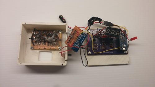
My project is a scratch-built calculator using an Arduino Micro as brains. As you can see in the picture above, the Arduino is connected to a PCB. This PCB is based off of this circuit that I found online, and LMR member Duane Degn was very kind to design the PCB for me in DipTrace. More about his work on the PCB can be found at this forum thread.
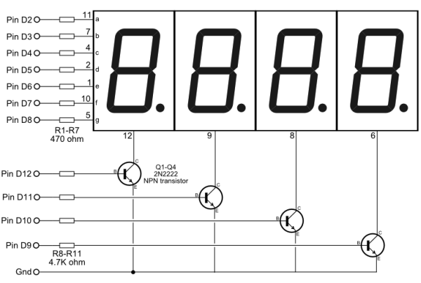
The calculator's display is made up of three multiplexed 7 segment displays (see circuit in link above). This means that any numbers entered cannot be more than 3 digits, and the result of the calculation cannot surpass this boundary either.
Finally, there is a 3x5 keypad matrix, connected to the Arduino through a WaveShare PCF 8574 I/O Expansion Board, and all of the components are mounted on a 3D printed case.
Unfortunately, programming is far from being my strong suit and I was hoping that someone could help me with the coding aspect of this build.
UPDATE AUGUST 31ST, 2015
I've been having some trouble programming the calculator. Whenever I try programming the Arduino Micro via USB ASP, I get an error message saying that it couldn't find an Arduino Leonardo, but I have selected Arduino Micro and USB ASP as programmer in the IDE. I'm using Arduino IDE version 1.05 on Windows 8.1.
What could be the problem?
Cheers! :-)
RobotGoose
Thanks for your
Thanks for your response!
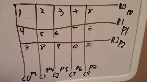
Here is the mapping of the keypad matrix. The pins indicated connect to the I/O expansion and not to the Arduino.
Cheers!
Here is the rest of the
Here is the rest of the schematics, as you requested.
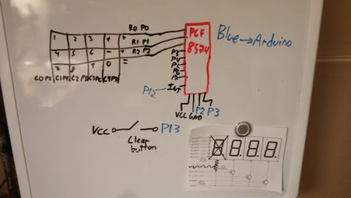
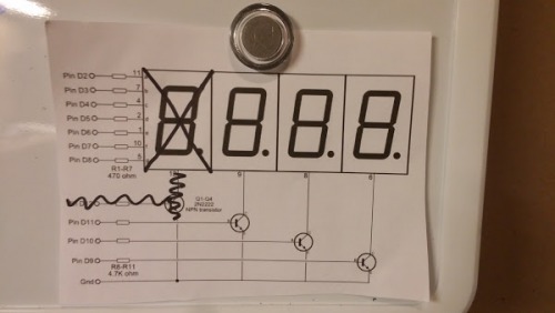
The second picture can be found here.
Sorry for my sloppy handwriting :P
Thanks again!
I’ve already found some
I’ve already found some sample code off the web for each for the display and the keypad that I’ve tweaked to fit my needs.
Unfortunately, for the display, an L appears on the third display, when the code was actually supposed to be a countdown.
For the keypad, there is no library for the I/O expansion that I have that works with the keypad.
Would it help if I linked you to both sketches, or should I just start from scratch?
Thanks!
I tried programming the
I tried programming the Arduino, but whenever I upload, it gives me this error message.
processing.app.debug.RunnerException: Couldn’t find a Leonardo on the selected port. Check that you have the correct port selected. If it is correct, try pressing the board’s reset button after initiating the upload.
at processing.app.debug.AvrdudeUploader.uploadViaBootloader(AvrdudeUploader.java:153)
at processing.app.debug.AvrdudeUploader.uploadUsingPreferences(AvrdudeUploader.java:67)
at processing.app.Sketch.upload(Sketch.java:1671)
at processing.app.Sketch.exportApplet(Sketch.java:1627)
at processing.app.Sketch.exportApplet(Sketch.java:1599)
at processing.app.Editor$DefaultExportHandler.run(Editor.java:2380)
at java.lang.Thread.run(Thread.java:619)
I tried pressing the reset button, but it didn’t work. Also, I’m using the icsp header on the Arduino to program since I damaged the micro usb port, so now I’m using a USB ASP programmer, which I selected in the Arduino IDE.
Why am I getting this error message?
Thanks!
I’m using Arduino IDE
I’m using Arduino IDE version 1.05 on Windows and Arduino Micro is indeed selected. However I can’t seem to be able to select the COM port. I’ve spent hours Googling solution but none seem to work, I keep getting the same error message.
Thanks!


