

I’m not sure I dare try but from your experience is it possible to heat treat small mechanical PLA parts like these without warping them?
Also what does your hot air rework station look like? The kind that is used for surface mount soldering? I’ve never used one. How would you go about finding a good one?
I’ve experimented with a hot air gun but it doesn’t feel like the right tool for this. Not enough control.
It tends to burn off very thin strands, and smooth layers. If you keep it pointed at a specific spot for long, it would certainly melt. It also makes great work of areas where support material have been removed.
The one we use with PLA: robotshop.com/en/hot-air-sm … ation.html
Heats up in seconds, and variable temperature control.
The idea would be to smooth out the layers for a better finish, nothing more.
Unfortunately don’t have a before / after image, so take a look at:
youtube.com/watch?v=cjujx7dlyOk
It’s certainly not the “best” tool for the job, and a quick search reveals there’s no “ideal” way yet.
Lets see if this works then…

and assembled…
https://www.robotshop.com/forum/download/file.php?mode=view&id=8243&sid=6ef56690440c115d2bdffa45da8beb0a

First attempt at printing something for the palm. It’s kind of like a construction kit part or something and I’m not completely satisfied with the design but my hope is that since I’ve left some extra mounting holes I can design a cool cover for it which will rectify some of it. I sure hope the print doesn’t fail.
I haven’t yet designed the wrist but I left plenty of mounting points for it which I hope will suffice eventually.
So yeah. “hope” is the keyword here but I couldn’t find a way forward otherwise.


Printed just fine although it went well into the night and I don’t really trust my printer enough to leave it alone. It feels super strong.
I’m quite glad it didn’t warp or curl up at the corners at all. I’ve learned that rounded corners and less contact area can help prevent that.
Getting it off the print bed was a bit of a challenge.
Btw the printer here is a chinese <$200 kit prusa i3 clone that I built (assembled), modified somewhat and calibrated myself.
It came in many hundreds of parts and complete with a very faulty assembly manual.
I’m printing with a 0.6mm head and 0.3333mm layers. It’s actually printing fairly cleanly. There’s a tiny bit of webbing or loose threads here and there but that’s just because I’m skimping on the supports.

A few more small bits and bobs to print. Assembly in progress.

assembly wip

Very “Terminator-esque” indeed.
[font=Arial, Helvetica, sans-serif][highlight=#ffffff]2304g so far … and it’s not even it’s final form  … feels really heavy[/highlight][/font]
[font=Arial, Helvetica, sans-serif][highlight=#ffffff]Also I’m going to trim the belts at some point but I just didn’t know until now how long I was going to need them exactly.[/highlight][/font][font=Arial, Helvetica, sans-serif][/font][font=Arial, Helvetica, sans-serif][highlight=#ffffff]Now that I’m this far I’ll have to make a video of it crashing or trying to crash a beer can or something I guess.[/highlight][/font][font=Arial, Helvetica, sans-serif][highlight=#ffffff]It would be cool to make a control board for it with knobs for each servo. I don’t think it would make sense to try to go the whole gesture and MRL route.
Those extra holes in the hand … this is where I plan to attach stuff that I haven’t designed yet. The two rows of 5 holes are for wrist and the rest are for a decorative cover plate including the ones on the knuckles.
I have a very special design in mind for the wrist. I have no idea whether it’s going to work so I’ll have to experiment in miniature first.[/highlight][/font]


Parts list for 1 finger:
18 ball bearings
28 bolts, 36 for thumb
26 nuts, 34 for thumb
5 pull springs
1 10-turn pot
1 servo, 2 for thumb
1 M3x10 bolt
4 M2x8 bolt
4 M2x12 bolt for thumb
15 printed plastic parts, 16 for thumb
- 1 big printed plastic palm plate
40cm of 9mm HTD3M belt
TOTAL:
90 ball bearings (4x11x4mm)
148 M4 bolts in various lengths (20, 30, 40, 50)
138 M4 nuts
5 M3x10 bolts
20 M2x8 bolts
4 M2x12 bolts
25 pull springs in various sizes
5 mexican 10-turn pots
5 servo motors (PDI-6221MG-360 continuous rotation servos + the disk shaped attachments)
1 servo motor (PDI-6221MG-180 + the disk shaped attachment)
77 printed plastic parts
200cm of 9mm HTD3M belt (NB! not regular printer belt. This one has bigger teeth.)
I like modelling the hardware and components that I plan to use in a design. Maybe it’s possible to find models online but I like the exercise.


So this is going to be the control box. I have a few more pots than I’ll need immediatelly but maybe I’ll need some of them later.
I’m also printing parts that attach to this one and will house an arduino mega.
I discovered that the Arduino megas I have are cheap chinese copies so the geometries are slightly different from the models online. So I had another excuse to model something.

[font=Arial, Helvetica, sans-serif][highlight=#ffffff]Starting to come together.[/highlight][/font][font=Arial, Helvetica, sans-serif][/font][font=Arial, Helvetica, sans-serif][highlight=#ffffff]There are 3 main components:
]Hand/:m]
]Hand controller/:m]
]Remote (on a long cable)/:m]There are 2 arduinos: 1 in the hand controller and 1 inside the remote. The one inside the remote will send digital data to the hand controller which will use this + finger position from finger pot to move the servos in the hand.


[font=Arial, Helvetica, sans-serif][highlight=#ffffff]Just finished programming the arduinos and testing for the first time.[/highlight][/font][font=Arial, Helvetica, sans-serif][highlight=#ffffff]Everything works fine except for one pot that seems to rotate freely and get out of alignment almost immediately. So ring finger doesn’t work at the moment.
First video on my instagram: instagram.com/lumikaarel/[/highlight][/font]
[font=Arial, Helvetica, sans-serif][/font]


Was not thinking it was so massive (nice to have a MEGA next to it).
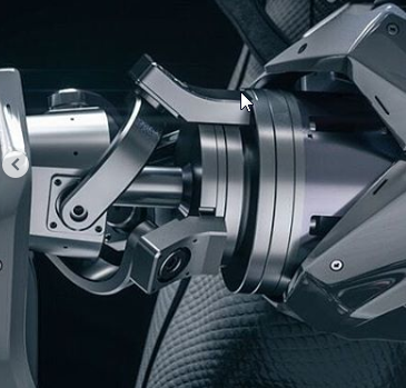
So I’m trying to come up with a design for the wrist and I found a cool design some time ago that I wanted to try.
So far haven’t found a person online who could tell me anything about it. The author doesn’t reply etc…
Decided to design a quick mock in fusion 360 to study how this works.
As soon as I defined all the joints everything went red and all the joins hate each other.

I’m starting to think that it may be impossible with regular bearings and may require ball joins everywhere.
If your CAD software allows for motion, you can always check to see it’s operating as desired. As Eric had indicated, the only thing that seems close enough seems to be a variation on a swash plate where the connection points of the links are offset. Might be some type of three point universal joint or variation on a Stewart platform? Dunno, sorry. Still looking forward to seeing the project materialize.