The other day I found this in our local garbage dump:
I have been trying to figure out its wiring diagram using a multimeter.
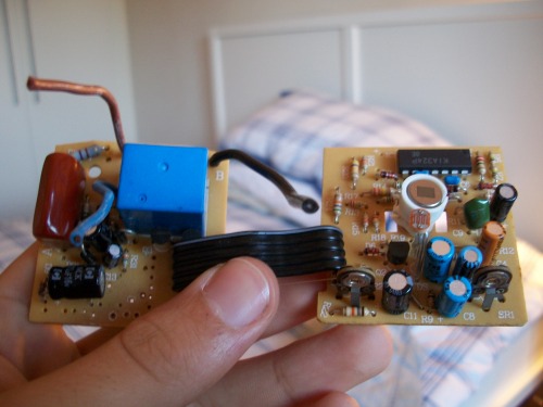
I know that all that is on the left is power control and everything on the right is to with the PIR sensor itself. There are 5 wires connecting the left bit to the right bit, 2 of them connected together so that makes 4.
1 of them will be V+, 1 will be G and I believe one will be to trigger the relay, what the last one would do is anybody’s guess.
I am wondering if I should try to get this circuit working or should I just slvage indidual parts such as the PIR sensor, 2 variable resistors, mini LDR and a bunch of resistors and caps?
I’d go for pulling it apart I’d go for pulling it apart myself, much easier to build a circuit that does what you want it to do than to change the behaviour of an existing one. Having said that it’s probably a good idea to take a look at roughly how it’s put together, that might give you some good ideas on how to use the parts.
I’m with TeleFox on just I’m with TeleFox on just pulling it apart. However, if you want to figure out how the circuit worked as a learning experience, I’d start by identifying the most complex part, which is the IC at the top-right in your picture. Look up that chip and trace all the connections one by one between all the components and you will have a schematic.
I think I will go with pulling it apart, I may not learn how this circuit works but by rebuilding one myself I will hopefully learn a bit more usefully knowledge.
But thanks for the tip, might be interesting to try it.
The board on the left has the relay for controlling the light. The brown capacitor takes the place of a power transformer, (much cheaper). You’ll probably find one end connects to the mains power and the other end goes to a diode. There will also be an electrolytic cap and probably a small 3-terminal regulator, (looks like transistor) to provide either 5 or 12 volts, (look at markings on regulator or relay to determine this).
The PIR board itself should operate with + - and one lead will be the output to the relay, (through another small transistor). The two pots will be for delay and sensitivity. The better ones have a photocell, (only works when dark), and a multiposition switch for several modes, (including “walk test”).