

*///This Robot is a work in Progress\\\\*
I will upload a video of it once I complete the robot.
Update: I just drilled two holes on the head for the ping sensor and mounted it. I loaded up the code and nothing happened ): . So I am going through a series of test to see what is working and what is not. I ran the ping sensor example and everything worked and I got readings. Then I went on to the pushbuttons and used the button example and both are working. I am going to try out the motors soon. If that doesn't work then I am going to re-check all of the connections and solder points. If all of the connections and solder points work, I am going to then go through the code, until I see a mistake.
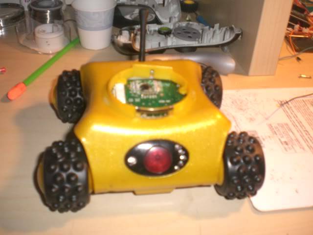
This is my current and first robot.I am 14 years old. I originally saw a video of a rumblebot on youtube with a ping sensor. I was going to follow the directions but I didn't have a rumblebot. Oh sorry I forgot to tell you guys what a rumblebot is. A rumblebot is a old radio controlled car. So I was looking everywhere for one but couldn't find one. I was about to buy one of ebay but I went to my friends house and he had one laying around. He said I could have it, what are the odds of that?
To build this you will need
- Arduino microcontroller
- Rumble-robot
- Parallax Ping Sensor (you can buy this at Radio Shack or somewhere online for about $30)
- 2 Push Buttons
- 100 ohm resistor
- Led (optional)
- Heat Shrink tubing
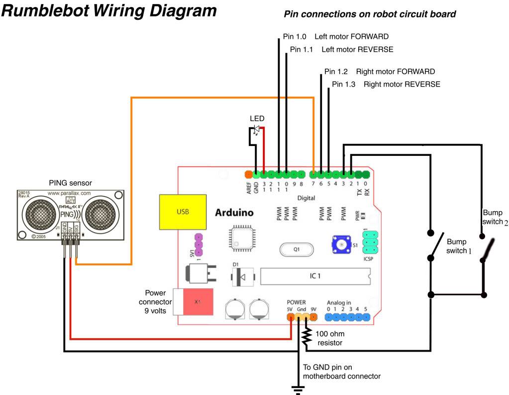
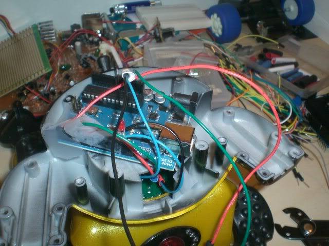
Hopefully the schematic will be uploaded correctly. To open up the rumblebot you need to unscrew a screw in the back of the head. Once that is unscrewed then you can take the head off and you will see the built in h-bridge and a rainbow wire cable. To take out the rainbow wire cable thingy use a flathead screwdriver and you can force it out. There is four solder points that are needed on the big black blobs. Solder wires to the points 1.0, 1.1, 1.2, and 1.3, Connect 1.0 to digital pin 11. 1.1 to pin 10, 1.2 to pin 6 and 1.3 to pin 5.
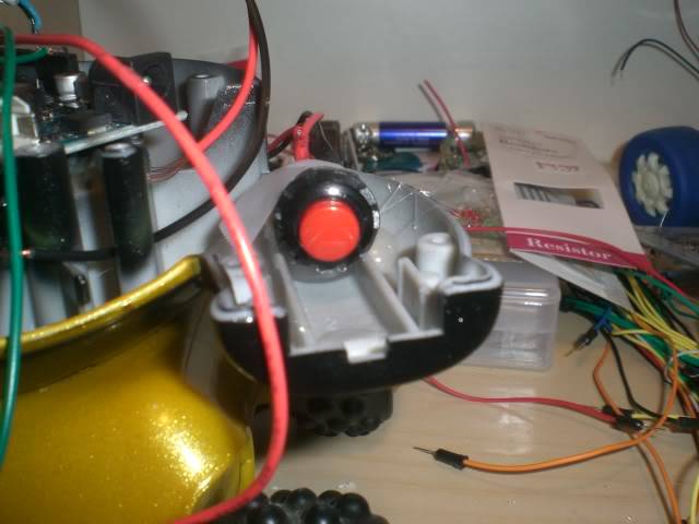
The two pushbuttons go behind the two arms. If you want it to all fit your going to have to shave off the back part of the arm.Then solder two wires to each of the ends of the button. Do this on the other button. Connect one of the wires into digital pin 2. On the other button connect one of the points to digital pin 3. The two other wires on each of the buttons are going to be soldered together. Then solder the 100 ohm resistor to that point that you just soldered.
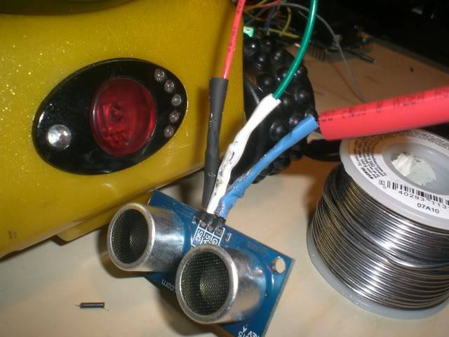
Now we need to solder the Parallax Ping sensor. It's pretty straight forward with the Ping sensor because you only need three points, Signal, 5 volts, and Ground for it to work. So solder a wire to the 5 v point on the Ping sensor and connect it to the 5 volt pin on the arduino. Now solder a wire to the sng point and connect it to digital pin 7. Now solder a wire to the point labeled gnd. On the Circuit board where the ribbon cable was pulled solder a wire on the 3 connector, this is ground on the circuit. Solder the two wires ground from the circuit board and gnd from the ping sensor and then connect it to ground on the arduino.
I want to make this clear that this is not my idea or website, I followed a video on youtube, this one specifically, these are NOT MINE.
http://www.dinofab.com/rumblebot.html
http://www.youtube.com/watch?v=rSHpy9Yql9M&feature=related
http://www.youtube.com/watch?v=tYRd0_7p-IA&feature=mfu_in_order&list=UL
Comments and suggestions welcomed (:
Here are some images:
Navigate around via ultrasound and two pushbuttons
- Control method: autonomous
- CPU: arduino uno
- Power source: 9 volts
- Sensors / input devices: Parallax Ping)))
- Target environment: indoor
This is a companion discussion topic for the original entry at https://community.robotshop.com/robots/show/rumble-robot-first-robot