

This project is my first foray into robotics and electronics for that matter. My goal is to end up with a platform for AI experiementation. I plan to add GPS and a camera for use with OpenCV shortly. I'd like to have the robot remember locations internally and externally where it has been and remember people with whom it has interacted. Lofty goals! I am using 2 MSP430s to control power management and the motor controller. The Raspberry Pi communicates with the MSPs over i2c for power management and SPI for the motor controller.
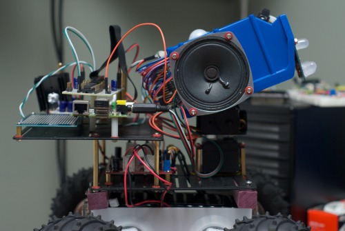
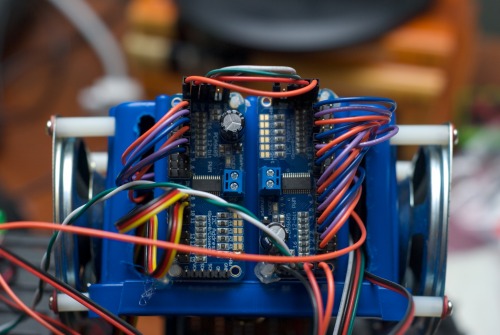
I opted to build the robot on the Dagu Rover 5 chassis with 4 motors/enoders and swapped out the tracks for WildThumper wheels. I had intended to build a motor controller circuit from scratch, but after figuring out what was involved, I made picked up the dagu motor controller (on the lower plate in the image above).
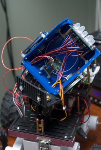
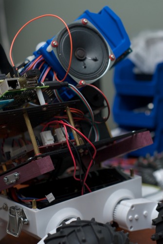
I used a Lynxmotion pan/tilt bracket combination and took a dremel to a parts bin for the head. As luck would have it the dividers that came with the parts bin proved useful in mounting the head in such a way that it can be easily removed for adding additional sensors and wiring. For sound, I used 3" speakers and a class D amplifier board from adafruit.com and wired that directly to the audio output of the Raspberry PI. I am currently using the espeak api for text to speech.
The "face" of the robot is 7 10mm RGB LEDs controlled by PWM. As I wanted to control the LEDs individually, I needed 21 pins of PWM. Since the Raspberry PI only has a single PWM pin, I mounted two 16 channel, I2C controlled, PWM breakout boards from adafruit.com on the back of the head to support the face and pan/tilt servos.
The following image shows the Raspberry Pi mounted on the top proto plate with the audio out running to the class D amp, mounted inside the head. I mounted a GPIO breakout PCB on top of the RPi and added an MCP23017 for additional GPIO.
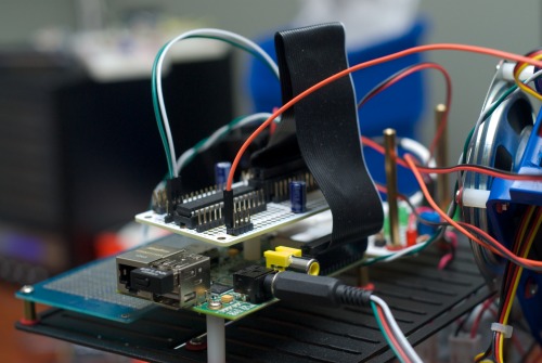
I have been writing and debugging the majority of GPIO specific code on the Raspberry Pi directly, as opposed to cross compiling and copying over. In order to avoid constantly having to swap in batteries, I added a 2.1mm power jack for an external DC power supply, as well as a connector for the battery. I added a DPDT switch (visible in the image below) to the chassis to switch between the battery and external power supply. I have a PCB with 5v and 3.3v linear regulators and intend to add an MSP430 to switch the power on and off and then connect the motion sensor to the MSP so that the robot will sleep after a period of inactivity and wake when it detects motion. While it is possible to power the RPi over the 5v GPIO pin, I cut up a mini-usb cable to power the RPi over usb in order to keep the fuse and onboard power conditioning in the circuit.
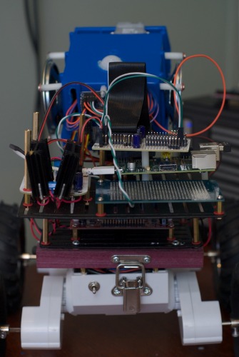
The Dagu Rover 5 chassis has room between the motors for a fairly large battery. I am using a 7.4v 3600 ma/h LiPo and wanted a quick release method of getting at the battery. I don't have metal working abilities, so I opted for 2 pieces of Purple Heart wood at each end of the proto plate and a couple of box latches for attaching to the chassis. I haven't gone over very rough terrain yet, but when attached it is quite solid, and gives easy access to the battery for charging.
- Actuators / output devices: 2 servos, 2 speakers, Dagu Rover 5 tracked platform (4 motors 4 encoders)
- Control method: IR remote and autonomous, WiFi
- CPU: Raspberry Pi
- Operating system: Occidentalis v.02
- Power source: 7.4 3600 ma/h LiPo
- Programming language: C++, C
- Sensors / input devices: Sharp IR, Photoresistors, IR Remote Control, GPS, maxbotix ultrasonic, Parallax PIR Motion Sensor
- Target environment: indorr and outdoor
This is a companion discussion topic for the original entry at https://community.robotshop.com/robots/show/rpi-rover
 Looking forward to more information. Keep it up.
