How can I determine the angular acceleration of each rotating joint with the problem that the acceleration of the ending effectors is always set to 1.2 m / s ^ 2? I do not really understand the factor of safety that you default to 2. And what formula is this factor of safety put into?
Thanks for taking the time to reply !!! I love you !
How can I determine the angular acceleration of each rotating joint with the problem that the acceleration of the ending effectors is always set to 1.2 m / s ^ 2?
Can you explain a bit more? The 1.2m/s^2 is your own requirement? If so, you would need to determine the motion of the end effector itself as that affects the angles of rotation of the other joints, and therefore their angular acceleration. For example, you can rotate the end effector around the elbow joint without moving the shoulder, or rotate the end effector around the shoulder without moving the elbow.
I do not really understand the factor of safety that you default to 2. And what formula is this factor of safety put into?
This was included as the equations are a simplification of reality. The robot arm will have inertia due to the weight of all parts, and as such, the torque required at each joint will be more than what’s needed to support a payload at full extension. The arm will need need to be able to accelerate from this (static) position against gravity. When reaching that “worst case” position from above, it will also need to accelerate against gravity. Additionally, electromechanical actuators tend not to be very efficient (at least the less expensive spur gearing coupled to a brushed DC motor), and can easily be in the order of 50% or less.
The guide is meant for people who have not begun the process of selecting parts, so the weight of each actuator, the weight of each joint and many other factors are simply not known and cannot be estimated. It’s intended to give the reader a good estimate using “napkin math” of the torque needed at each joint, without being able to include many other factors which are needed only once parts have been selected.
Since you’re curious about the equations themselves, press F12 on the Robot Arm Torque Calculator page, and the equations used are towards the bottom under the function DTArmCalculate(). The equations themselves are quite simple and use only basic equations of the sum of torque acting on each joint. It’s up to you if you want to factor in anything else like the proposed “safety factor”.
Hi @cbenson, how do I find give a mathematical representation of the load torque and transient
torque which is required to include the determination of the moment of inertia for the system with 3-dof?
@Jdiknight Welcome to the RobotShop Community. By “3DoF”, do you mean an articulated arm with shoulder / elbow and wrist, or a “3DoF” like:
Regarding moment of inertia, you’d need it for each actuator and for each link. The more links you have, the increasingly complex the calculations become. As for the shape (for inertia calculations), use something “relatively close” (rectangle normally works well enough), unless your 3D CAD software can calculate it for you.
It would be interesting if you could treat each link as “massless” to save a ton of calculations (and only take into account the “heavier motors” like the ones in the wrist, as well as the payload (which is now only moving in 2D). On the plus side, the inertia calculations are a bit easier since there are fewer degrees of freedom.
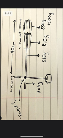
Hello @cbenson I am struggling with calculating the the required torque for my robot arm (I tried to follow the tutorial but I am confused at how to apply it to my robot arm). This is a diagram of my arm below:
“Counter-torque” needed to keep the arm horizontal against gravity would be:
0.535Kg x 45cm (assuming the mass is centered) = 24.075 Kg-cm
0.81Kg x 50.5cm (90-22-35/2) = 40.905 Kg-cm
0.55Kg x 79cm (90-22/2) = 43.45 Kg-cm
0.5Kg x 90cm = 45 Kg-cm (payload?)
Add them up to get 153.43 Kg-cm. However you show there’s a mass on the opposite side:
0.264Kg x 15cm (30/2) = 3.96 Kg-cm
Therefore the torque needed at the pivot would be:
153.43 Kg-cm - 3.96Kg-cm = 149.47 Kg-cm (let’s round it to 150 Kg-cm)
If you wanted to raise the arm, the pivot would need to produce more torque than 150 Kg-cm to produce a change in velocity (i.e. acceleration). To calculate that torque is more involved since the equation is Torque = (Moment of Inertia) x (Angular Acceleration). A slow acceleration involves less additional torque.
Moving 45 degrees in one second doesn’t actually directly give you acceleration (radians per second per second) but rather the average angular speed. The harder part tends to be calculating the total inertia of the system.
Effectively the inertia of each of the masses (and the support rod). Assuming the motor is not rotating at high speed (and it’s not a flywheel), its effect on the inertia is likely to be minimal so it’s up to you if you want to estimate it and include it. Remember, even with all the calculations, it’s best to multiply the calculated value by a “safety margin” to account for inefficiencies etc.
When it comes to inertia formulae, it’s dependent on the shape, the rotation, where the weight is located etc. You’ll need to look it up for each unfortunately. Example
Note that the formula I = (m*r^2)/2 is associated with a disk rotating about the center, which is not the case in your drawing (no disk). You’ll likely be using the formula for a “rod”, “plank” or “satellite”. In inertia equations, “R” is associated with the object’s radius, whereas “L” is the length from the axis of rotation to the center of mass of the object.
Provided the arm is horizontal to the ground, the torque needed is only a factor of the acceleration needed. If you really want to do the calculations, it’s back to Torque = (Moment of Inertia) x (Angular Acceleration).