

Hello LMR,
I just want you to show one of my current projects. It's a simple light-seeking robot that compares the input voltages oft two Pin's wich are connected to two LDR's. If more light is coming to the right one, the robot drives to the right.Same for left.If both values are nearly the same it will drive forwad.
The video shows a quick demonstration where I just point a flashlight to the ground and the robot drives toward it.
The components are :
2: 3V dc motors
1: H-bridge
1: ATMEGA 8
1: old pencil
some: wires
2: LDR's
1: pressbutton
1: lever
2: 10KOhm resistors
1: 5V regulator
2: capacitors (16V 100uf)
1: LED
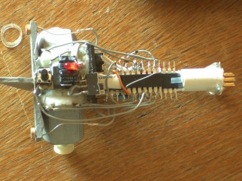
The lever is used to turn the power on/off, the button for switching the modes.For now it has got just one mode (lightseeker) but I'll add some more modes (control it with my RasPi, ..). As you can see it's designed to be powered by a 9V battery but my rechargeable batterys can't provide the needed current (600-900 ma) so I'm just using a 7,4V 600mah LiPo battery.
In the back you can also see the plug for the programmer.I'm using Atmel Studio for programming and a simple and cheap (3$) USBASP programmer.
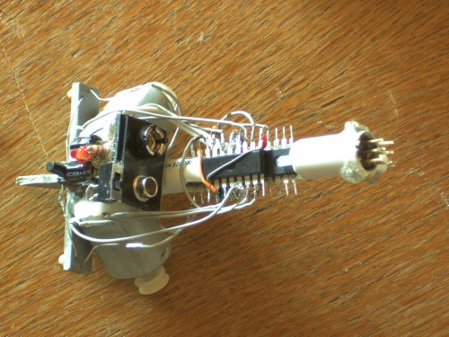
I'll also add the code later but for now another picture :
Driving towards a light source
This is a companion discussion topic for the original entry at https://community.robotshop.com/robots/show/robobike-1-0