

Introduction
Now, for the next in a series of reviews on Ro-Bot-X's boards. This one is on the beta version of the uServotino. It is an ATMEGA328 custom board with the Arduino bootloader pre-installed.

The Kit
Ro-Bot-X's boards are usually available in three options.
- Stand alone board (un-populated)
- A kit with all of the components needed to populate it
- Fully assembled:
Since this is a beta and not available for order yet, I can only assume that he will offer the same options. I generally recommend the kit, unless you already have most of the part in stock yourself. Ro-Bot-X provides the kit parts at a price I couldn't beat searching for them myself.
Here's what you get:
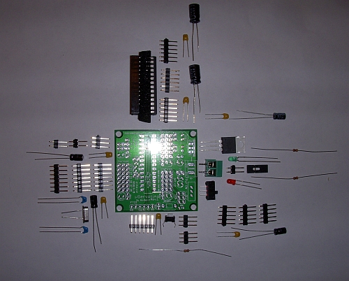
- (1) uServotino board
- (1) ATMEGA328P-PU microprocessor with the Arduino boot loader and blink sketch pre-loaded
- (1) 28 pin dip socket (for the above microprocessor)
- (1) Two-connector screw terminal (for power)
- (2) 220uF 16V electrolytic capacitors
- (4) 10uF 25V electrolytic capacitors
- (7) 0.1uF ceramic capacitors
- (2) 0.022uF ceramic capacitors
- (1) 16 MHz crystal oscillator
- (1) 5mm green LED
- (1) 5mm red LED
- (1) LM294 1A low drop out voltage regulator
- (2) 1k ohm 1/8 watt resistors
- (1) 10k ohm 1/8 watt resistor
- (4) 6-pin male headers (for the sensors A0-A5 and the FTDI interface)
- (3) 7-pin male headers (for servos D2-D8)
- (3) 5-pin male headers (for servos D9-D13)
- (3) 3-pin male headers (for the ISP interface and part of the UART interface)
- (3) 2-pin male headers (for the other part of the UART interface and the D13 LED jumper)
- (1) momentary reset button
- (1) single pole, single throw power switch
- (1) jumper (to connect LED to D13, if desired)
The kit itself is no frills and no nonsense. You get parts in a plastic bag, without printed instructions. (Note: I wrote on the bag.)

For his other boards, Ro-Bot-X provides an assembly guide on his website. I assume that he will do so for the uServotino as well.
Assembly
Assembly was pretty easy, if you know how to solder.
One item Gabriel (Ro-Bot-X) pointed out to me is that the crystal oscillator needs to be installed so that it is slightly raised above the boards, otherwise it shorts out the two 0.022uF capacitors on either side. Gabriel intends to fix this on the next batch of boards.

I had no trouble working around this issue using Gabriel's instructions. Keep in mind that this is a review of a board under beta testing.
Finished Product
Here's another view of the assembled board.
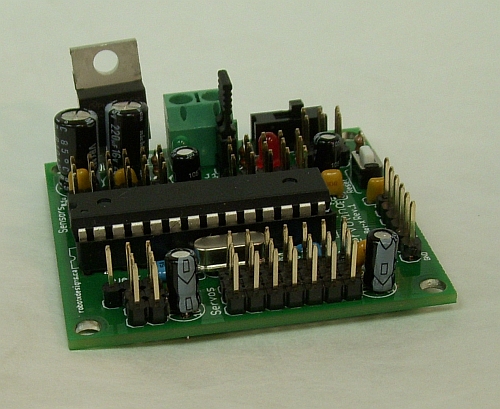
The 6-pin male header shown on the right side in the picture above is FTDI port. One of the ways Ro-Bot-X keeps this board small and keeps the parts cost/count low is to leave off the USB to serial translation circuitry you get on a Duemilanove or Uno. So to program the board, you need an FTDI to USB cable.
Everthing is clearly labled and the board layout is very compact. The board is only 2 inches square (just over 5 cm square, for all you metric types.)
Notes
Power
The low drop out (LDO) voltage regulator should keep you running with a clean 5V output down to 5.5V from your batteries. It supplies up to 1A, which should be fine for the microprocessor and any sensors.
Servo power is direct from the batteries, with 0.1uF and 10uF capacitors installed right next to each bank of servo ports.
Servo Test
I felt this wouldn't be a good review if I didn't max out the servo handling capabilities of the board. I had to scrounge up 12 servos, borrowing on from Penny and a couple from a Dagu Pan/Tilt I previously made.
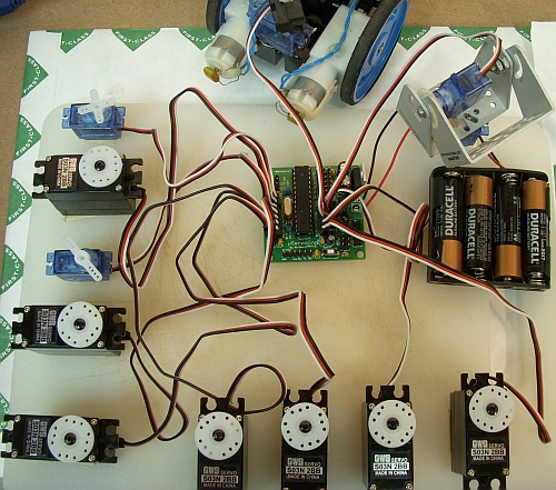
I borrowed some code that OddBot wrote to drive up to 48 servos on his Spider Controller. I simply commented out the extra servos in his code, so I could test with 12 on the uServotino.
In the video, you can see the servos all turn in sync, and seem to move smoothly. The batteries I was using during the test were 4xAA alkalines, which were down two about 1.4V each. I monitored the battery voltage while the servos were moving, and you could definitely see the effect of all those servos. However, the board performed fine througout the test.
Note: If you watch the video, you may see or hear the servos stopping right at the end. It turns out that one of my servo wires got crimped in the pan/tilt mechanism, shorting power and ground. Once I resolved this, everything worked fine again. It is interesting to note that the board survived the power shorting with no apparent damage.
Interfaces
All the interface pins are broken out on the 3-pin male headers along with power and ground. The power for the digital pins is directly from the battery, isolated from the microcontroller and analog pin power through the voltage regulator.
Filtering Capacitors
There are 0.1uF and 10uF caps located next to each of the two servo blocks, the analog interface block, and the D0-D1/UART port.
Silk Screen
The board is very nicely and clearly labeled in a white silk screen. I think the production boards will be Ro-Bot-X's preferred black on yellow background.
Concerns
No Power Jumper
I really missed the power jumper that Ro-Bot-X included on his Robot Builder's Shield and uBotino. Every time I download a new program, I'm concerned about leaving the FTDI cable connected, since power at this point is coming both from the on-board voltage regulator and the USB port of my computer.
I can switch the power of the uServotino off during download, of course. However, as soon as the sketch downloads, it starts to run from the USB power via the FTDI cable. There's not enough current capacity from the computer's USB port to support the attached servos.
Also, I often want to leave the FTDI cable connected during debugging so I can use the serial terminal in the Arduino IDE. I'm concerned that there could be a power conflict between the USB and the voltage regulator.
I've discussed this with Gabriel, and he said he'd look into adding a jumper for this like he did on his other boards.
Auto-Reset Not Working
Gabriel warned me that the auto-reset feature of the uServotino was not working properly, and I was able to confirm this. He has stated that he fully plans to have this resolved on the next release.
Purchasing
This board is in beta, and is not yet available for purchase from http://robotxdesigns.ca. Contact Ro-Bot-X directly if you are interested in purchase.
Summary
This is a very inexpensive (assuming Ro-Bot-X prices the board in line with his other designs) Arduino based servo controller. There are other servo controllers out there, but this one is easy and compact and gets you going with up to 12 servos, plus 6 analog inputs for sensors. It could easily be used as the basis of a walking robot, continuous rotation wheeled robot, or even a brass venus fly trap.
------------------------------------------------------------------------------------
Also see... the Robot Builder's Shield V2 Review.
... the uBotino Microcontroller Kit Review.
https://www.youtube.com/watch?v=IEixtE1UCXE