I just got another order of PCB's delivered, ones that I designed. New 3A power boards, IR beacons, on-board battery chargers but most importantly, an AWESOME new line-follow board. Just wanted to do a quick, little Walter update and show you what I am up to... We are getting very close to the wonderful final step of paint!
So here are the regular boards:
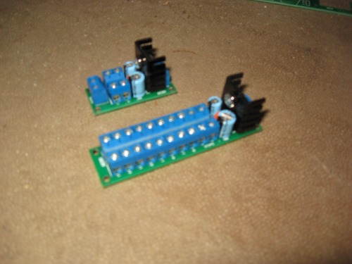
New Battery Charger. This is an on-board charger and will stay attached to the robot. It can power the robot as it charges the batterys, has an automatic trickle and even a data-out to show the state of charge (charge/trickle). I used this data-out to trigger a relay board which will be used to turn on my cooling fans. This charger circuit is simply bad-ass and can be confirgured in unlimited ways. It is based around a max712 and/or max 713. Here is the post all about it.
Next is my 5v 3A power boards. Nothing fancy here, just a regular volt regulation. I did add the nifty screw terminals to clean up a lot of the spagetti under Walter's chassis. One is for the major parts and the second is just for the servos.
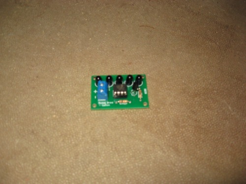
IR Beacon --Just an 08m, 5 IR LED's and a transistor.
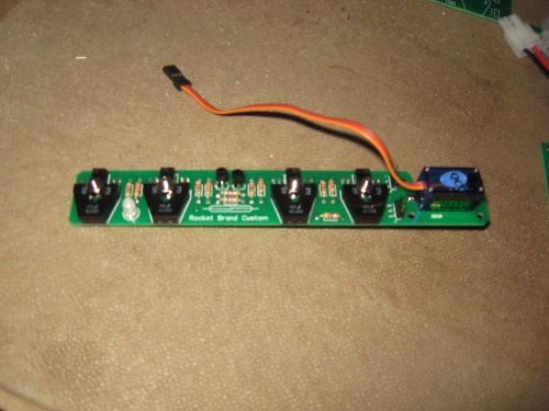
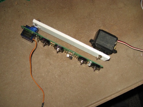
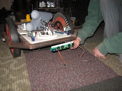
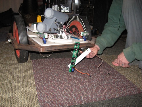
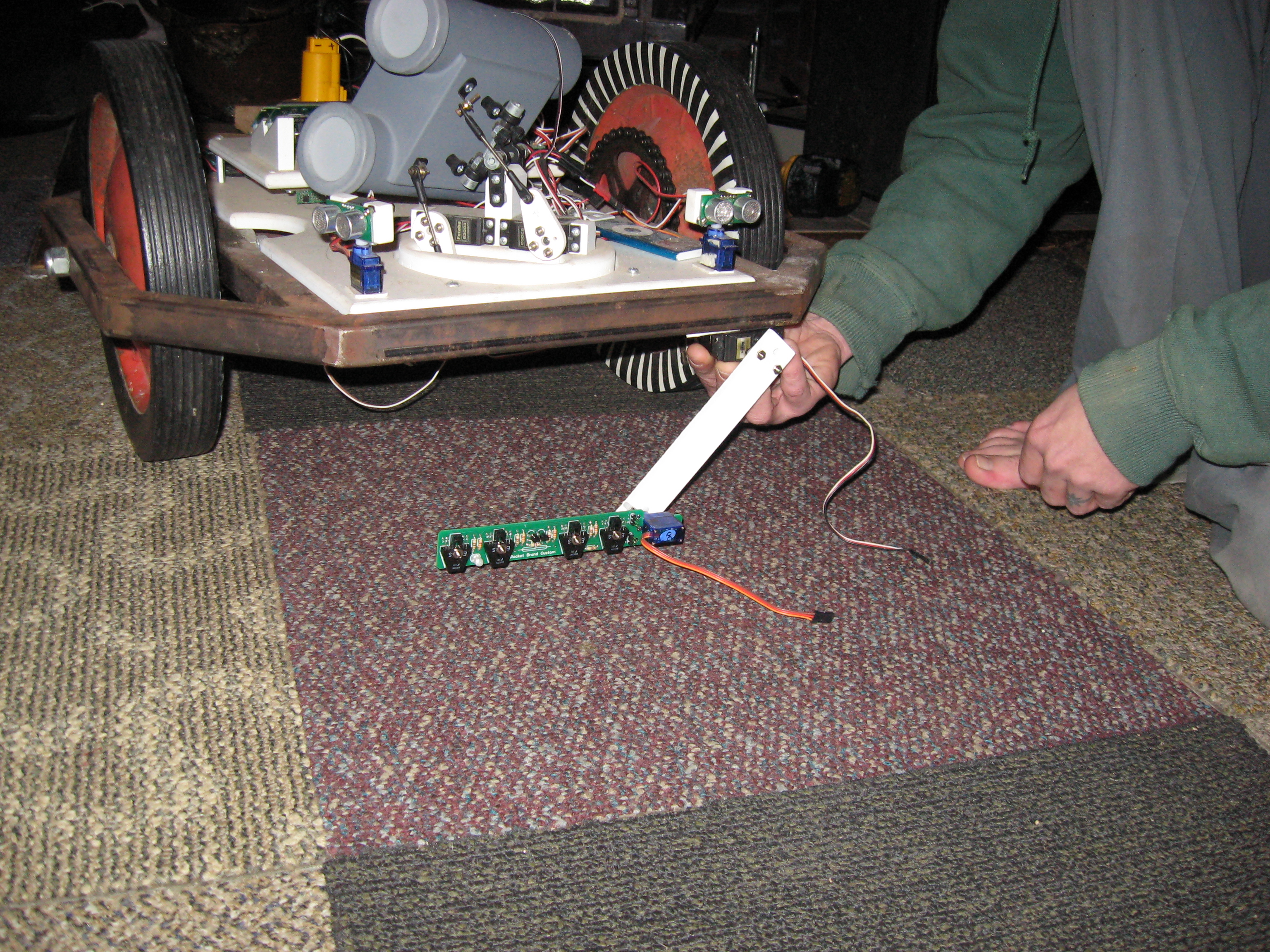
But now, here is the good stuff... New line follow system!! I designed the PCB to accept the mini servo with all mounting holes pre-drilled for me. In addition, there is a reed switch on the back which lines up with a magnet when the arm is retracted. This keeps the IR emitters turned off. When the arm is lowered, the magnet is moved out of the way and thus turns on the sensors. --Good stuff!
Keep scrolling down, the pictures should explain everything.
Diptrace and Sparkfun I used diptrace (with the free LMR member upgrade) to design the boards. I used sparkfun’s PCB service for fabrication. Sparkfun’s service is super-duper slow but it is wicked cheap and you can order just one board if you would like. --Oh, back to the diptrace thing: I had to custom-draw (by hand) a few of the components… The screw terminals, tact buttons and the IR sensors (encoders used on the line follow) were not in the library.
Pretty cool ideas, good Pretty cool ideas, good additions. If you used a parallel bar linkage on the line sensor, you’d only need one servo to lower the module while keeping it parallel to the ground (and robot chassis).
@robologist I thought the same about the parallelagram thing… I didn’t have the width, though -When the unit was retracted, it stuck out too far to the side. With the 2nd joint, it halves the distance.
That doesn’t make a stable voltage? Those IC’s are for recharging batteries, not to make voltage 1 go to voltage 2… At least that’s what I can make of it…