

Hi i am working on project to get response of reflective object sensor when it is placed in front of some reflective surface and i am trying to display the results on oscilloscope.I connected reflective object sensor from optek with LM339 voltage comparator to get ttl waveform but when i connected it to oscilloscope panel it is showing me a straight line and when i placed non- reflective surface in-front of this this line goes down but i am not able to get a waveform.Please can you suggest me what more is required to get pulse.
@Casmat @Jbrunet I want a waveform which will show 0 level when LED not reflected light or a black surface is placed near this sensor and High level ( 5v) it will show when placed near the reflective surface .I am Placing this near continousily rotating filter wheel so at that point it should not show a straight line thats going up and down and am not able to find delay time .So my question is how i can find delay time between one filter to another filter it is taking .I am sending you the link for my set up lynxmotion.com/images/data/sld-v1.pdf (page 4)That i have made .So please suggest me what can i do?
Thanks!! I want to find the delay time between one filter to another filter as i am using this Reflective object sensor to sense the filter wheel .Without microcontroller it is possible to calculate the delay time between one filter to another filter when my filter wheel is keep on rotating continousily.
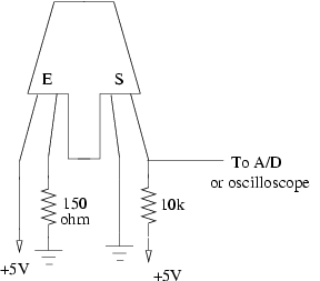
@Casmat Thanks a lot for reply!!Firstly, i connected only the sensor with oscilloscope and set-up that i have used for this ccrma.stanford.edu/~larrywu/course/250a/lab5/index_files/optical.png but i have connected 220 ohm resistor with anode rather than to connect with cathode of emitter .To externally triggered my camera a ttl waveform is required for that i have seen your Single line detector where sensor is connected with LM339 and i have made the same set up using voltage comparator LM339 and even i am using different sensor OPB703 and in your set up is connected with OPB745 darlington transistor so connected opb703 to one more transistor.Please suggest me if i only use the sensor without voltage comparator what more is required in my set up that i have sent to you and from this can i trigger my camera?
I want to trigger my camera and that trigger signal will be sent to camera trigger input pin.Please can you suggest me is there any other way to trigger my camera right now i am using this reflective object sensor to find the delay time that is required to stop the camera from capture the image when there is a delay between one filter to another filter or using this sensor it is possible to get the right results .
Since the output of your circuit is relatively linear you may not be able to get a sinusoidal waveform.
Basically you would obtain a square wave. If you need to calculate the time between transitions, we suggest a microcontroller or PC interface, unless your scope is sufficient for your needs.
A microcontroller would be ideal, unless the scope has that functionality. You can count between transitions and even output to a PC serially to graph it. If you aren’t sure where to start, Basic Stamp, Basic ATOM, Arduino and PICAXE are great for beginners. We do have many microcontrollers to choose from!
Why are you expecting anything else than a flat line at a certain level? The output of your system is proportional to the reflectivity of the object at the input (which is constant in your case)
You could also manually measure the signal with an oscilloscope, You would need to connect the sensor directly to an oscilloscope (you do not need the LM33). Make sure it is powered properly and that all your scope settings are fine for measuring the frequency and the amplitude (5V) of the signal.
Also, make sure that you sensor is capable of detecting the wheel properly and that it is not going to fast for it.
Basically if you could perceive the difference between high and low reflectivity with your sensor, there is no reason why you could not sens a (perhaps rapid) succession of high and low reflectivity).
Let us know your results! You could post some pictures about your setup.
So you are sooting pictures each time the high (or low) reflectivity is detected?
If you are trying to take pictures at a preset frequency (i.e. like in time lapse photography), using a microcontroller to dictate the frequency would be the best approach: give Arduino a try