In my current project I have a rotary switch as a sort of menu selector.
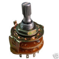
I could use 6 IO pins to read the state of the switch but with adding resistors I can find the position using one analog input pin.
This is probably common knowledge, but it’s new to me as I have never had the use for a rotary switch before. But for anyone that could have a use for it, this is what I did.
Between the contacts (in my case 6 positions) I added a 1k resistor. Then feeding 5V to the first value in the chain you get different voltage from any position in the resistor chain. This is easily read by an analogue input on any microcontroller.
So with using resistors and one analogue pin you can read any rotary switch position and with a couple of them probably make a very complex menu system.
Nice tip!MAKE did a whole
Nice tip!
MAKE did a whole series of videos on Basic electronics explained in a fun way, which Gareth collected in a post. It was recently updated with a video on switches, which mentions rotory switches. Your tip complements this nicely.
I love the Collin’s Lab
I love the Collin’s Lab videos and it’s highly recommended for anyone starting up in electronics.
This is and excellent
This is and excellent discovery!
(Quick digression: I also made this discovery around about the same time I invented “instant tea” using a corning process. Trouble is with most of these things, some other sod with far more money makes it to market first!!)
You’re right in that it’s a common technique (“resistor ladder”) BUT the amazing thing about “discovering” for yourself these things (rather than reading them off some textbook) is that it proves you have the “think-outside-the-box-ability!” Folk who “discover” like this rather than “plagiarising” from someone else’s discovery will invariably eventually discover something that some rich sod hasn’t already discovered!
I’m looking forward to watching yo do that! Thanks for sharing.
Thank you very much for this
Thank you very much for this comment. This is probably the one of the nicest thing anyone has said to me. And yes, if I had googled a bit I would have found that this is not new, but it’s still a great feeling figuring it out on your own.
Before IR
Back in the late 70’s, before IR remotes, RCA and others had wired remotes on their VCR’s. All the function buttons had resistors accross them, (different values), and the total resistance was read with an A/D converter. This gave you maybe a dozen functions with only 2 wires.
Same principle you can also
Same principle you can also use for tactile sensors on your robot 
While I will fall into the plagiarizing bunch,
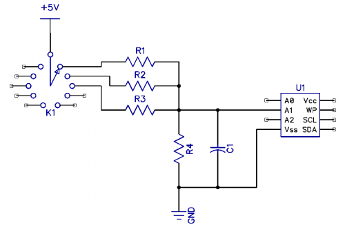
I have also run across pages that mention, rather than using an analog pin, one can also add a capacitor(connected to ground?) and then to read an input from a resistor ladder. First, one makes the pin an output and charges the cap. Then, switch the pin to input and measure the time required to discharge the cap. The R/C time constant will be different for different positions on the resistor ladder.
’Ground/bottom’ resistor
I would guess that you also will need at ‘ground/bottom’ resistor to make a voltage divider? If yes what resistor value did you use?
Correct me if I am wrong using this method will not create a linear input scale (not that there anything wrong with this).
Schematics
I guess it is similar to this:
Your probably right and
Your probably right and thanks for the input. I haven’t hooked anything up yet so I’ll be sure to add the ground resistor. But is the capacitor necessary or just good practice? Is it for debouncing?
Voltage levels
A quick calculation shows:
Position:
1: output = 1.25V
2: output = 1.67V
3: output = 2.5V
4: output = 5.0V
I would probably find resistor size that would give a more linear output. In my example I only use 4 positions but with 6 positions the following output voltages would be 1V and 0.83V.
I hope you can see where I am going 
Another solution
A different solution though you will need more different resistor values but are able to easier deside/calculate the output voltage for each position.
Debouncing
Yes, mainly for de-bouncing.
You should also in your code be prepared to handle the situation where the analog input is read exactly when you switch (between two positions).
I would guess that for one position the voltage on the input can change a little depending on the stability of you powersupply. So I would check for the values within ranges depending on your experiences.
A good article about de-bouncing (fo digital inputs though) http://www.ganssle.com/debouncing.htm
Good tip, Geir! Got me
Good tip, Geir! Got me thinking
O my god, what Pandora’s box have I opened here
Love to see your enhancements on this, as it seems to be an overlooked function here at LMR. I haven’t seen it used anyway.
Nice tip,
Nice tip, Geir! Thanks for finding time to share! 


