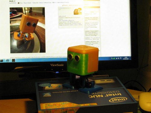
It's now over 18 months since the first BOB appeared strutting across K120189's worktop and I still haven't made one so I'm going to remedy that. However, now I've discovered its joys, I really like playing around with 3D CAD so I'm taking this opportunity to give Bob a facelift and a bit of a re-hash.
I believe that Kevin didn't have access to a 3D printer when he was designing Bob, so couldn't tinker with the design as much as he would probably have liked. However, I have and I have been. Please don't take the following as criticism of the original Bob - I love the look and the movement. He's a real gem of a bot.
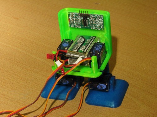
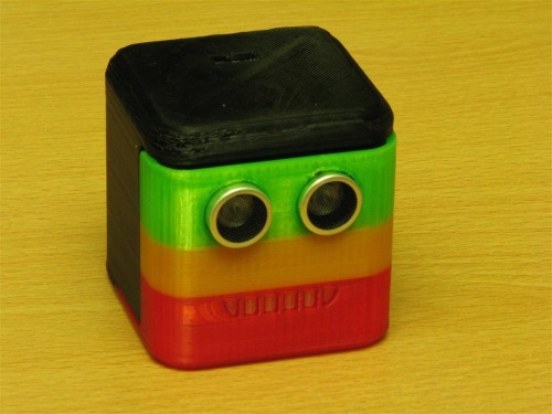
From watching the videos of existing Bobs, many have their brains or batteries on the outside. I want both to fit inside and my design has space for a 2"x2" (50mmx50mm) PCB, mounted on posts, and is also designed so the electronics can be fully assembled before putting the (clip on) headshell in place. Bob's legs have always looked a bit gangly to me (maybe that's part of his charm) but I'm moving the servo horns to the other side of the brackets (and the servos further into Bob) to reduce the side forces on the servo spindles. And the face - I can't decide whether my mouth design is smiley or sinister. Who knows what Bob is thinking?
For batteries I'm using 2 x Turnigy Nanotech 750mAh LIPOs connected in series and my Bob will have a Picaxe brainbox. I'll post files for the 2 main sizes of ultrasonic sensor in due course and will be adding to this thread as work progresses. As it is, I'm happy with the feet and brackets and almost there with the two parts of the head.
Oct 18th 2014:
I've been working on this as well as a couple of other projects, but recently suffered a bit of a setback. I'd fully assembled the servos and legs to the body and then ran some simple test code to waggle the servos a bit. It was so simple that I didn't test it first and when I powered up, all four servos went thud-wallop to the 0ms position, well beyond the endstops. I had forgotten to initialise the position variable before entering the movement loop. Result : Two stripped servos. Next time I'll simulate the code before applying the juice. (It looks like my comment to rwinscot was prophetic! ;¬)
Where is the inside pic of the other half of the head?
For a control board, if you don’t have one already, check out the board I designed for Maxhirez. I have a few spare boards yet from the first batch. I also have the stereo header.
Your board looks interesting - I hadn’t seen that before. I was planning on using the 28x2 module on a stripboard layout for its compactness, but a 20 pin 'axe would be enough for the job. Getting ready for work now but I’ll have a closer look later. (I’ll post a pic of the other half of the shell too.)
Birdmun, your board could have been made especially for re-Bob - It’s perfect! It would fit in with the motor connections at the US sensor end - No L293 fitted of course. I haven’t got a scale drawing of it but my approximation based on the hole pitch is just a gnat’s under 2" x 2". What is the distance between centres of the mounting holes? I’d be interested in a couple more of those if you have them too as they appear to be the ideal multi-purpose Picaxe board. I’ll PM you about it.
They are 50mm square. Center to center on the holes is 1.73 inches or 43.942mm.
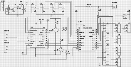
The schematic you are showing is a little dated. All four of the IO that go to the motor driver now have jumpers. The driver doesn’t even need to be installed. Maxhirez and ossipee have a couple boards each. I may or may not be out of heatsinks for the voltage regulator. The stereo plug is really the only bit I need to send to you, along with the board. Everything else is common parts.
Mind you (and everyone else) I am not trying to push my work. It just came to mind when you mentioned 2x2 and PICAXE.
I am a noob to robots, my Bob is on here, made from balsa. Looking at this (which I love!), I would comment about the gap between the feet. Would I be right to say the feet have more of a gap between them than you normally see in a Bob? My intuition is this will cause a problem in the initial lean of Bob to raise his other foot up?
As I say I am new and just starting to code my Bob, so far I’ve concluded you need the gap between the feet as close as you can but still allow the movement. I’ve added big weights high up either side of Bobs head and getting him to slowly lean has been a challenge.
I’d be interested in any comment about your thinking on the the size/position of feet. Thanks
You’re right. The servo slots and foot / bracket dimensions are the same but because I’m now positioning the servo arms on the other side of the bracket, the feet have moved a few mm outwards. I’ll fix it.
Just as an additional aside, look at the feet on this robot and the way they overlap/cross over the center line, interesting I think. Again, very nice work, I look forward to the rest of your build.
I think the overlap is neccessary in the robot in the video because it has fewer degrees of freedom than BoB. BoB’s foot servo allows him to sway his body to move the centre of mass to above the foot, so the other foot is free to move. Thor cannot do this so relies on the foot extensions to stay upright while the other foot is off the ground. The sway shows up brilliantly in Badji’s video.
It’s that first moment when the servo tilts that I am finding interesting. I think that if the gap betwen the feet is too big, the centre of mass will be too far outside the foot print of the foot and when the foot tilts the body mass over balances the tilting foot and keeps the weight onto the other foot.
In Thor the bits that extend inwards and overlap the centre line, if added to Bob, would ensure that when the servo tilts the footprint is wide enough to gently push the centre of mass over the tilting servo.
I agree that in videos of Bobs walking we often see a ‘dynamic’ sway of that mass that is quite fast and I am not saying ythere is anything wrong with that, but what I am interested in is a slower walk and for that I think you need feet that have a foot print that is as close to the centreline as possible - the other foot can help the initial shift by pushing down too and even if the gap is small, if you want a slow shift I think you have to use both feet to get the tip.
Hope what I am saying makes sense and I am not being a bore! Accept what you say - there are lots of Bobs walking very well with larger gaps and I also think that the dynamic swaying of mass is interesting too.
I made a prototype similar to Bob with two halves of a CD as the feet, and I had them spaced too far – for the first few degrees, it would stand on the other leg. Solution? Make the other leg tilt the other direction, pushing it off the ground past the few critical degrees. Hacky, but saved my prototype.
@deshipu - I think a slight push down with the other foot is elegant, and even if you have the feet close togerther I think you still need to do that for a slow lean to make sure the CoG moves across so its above the tilting foot.
I just have a nagging feeling there is another solution that doesn’t involve overlapping Thor feet or mechanically moving the weight in Bobs head somehow…
By the way, if you find a way of moving the center of gravity, you can get rid of two servos – the ones in feet – and just have the feet angled at a constant angle. With some mechanical additions, you can also have them both moved by one servo… So a tailed biped could run on two servos.
Ahhhg, sorry to read your 18th October update. With mine being made of balsawood, the threat of the servos destroying the knees and feet was so massive I remembered to centre everything. Sorry to learn that on a ‘real’ printed Bob its the servos that come off worse.
Nice job. I wish I could build Bob but the only problem is that I don’t own a 3d printer. Hey is there any chance you could build that without a 3d printer, just saying.