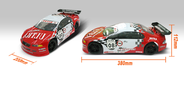
If you are refering to the
If you are refering to the am transmitter that comes with the car, that would be a 2 channel 1 way communications. You send out signals but get no feedback unless you attached something that could send data back, like a video camera proc connected to a tranmitter.
A Bluetooth/RF tranciever would give you 2 way communication which would allow for feedback to be transmitted from the RC car as well as instructions being sent to the car.
You would need to essentually replace the (RC)transmitter/reciever setup that you currently have with a setup that would allow for communications and control.
The processor that you use, pic, avr, arduino, picaxe, doesn’t matter as long as it can interface with the devices that you are going ot use…which shouldn’t be a problem. At any rate, yes the pic should be attached to the rc car itself.
Ex.
[[controlling app] computer]<–BT/RF_tranciever–> ///\radio signal////<–BT/RF_tranciever–>[uProc–>[servo/motor control[RCcar]]]
The controlling app(on the computer) could be anything from say a .net app, java, or processing which is what some folks here have started to tinker with. That would relay the signals via the BT/RF tranciever to the BT/RF tranciever on the RC car. this tranciever would be attached to the uProc(PIC if you like) which would then relay the commands to the contoll devices, like the servo and speed controller. You would most likely want some sensors on the buggy as well which the uProc would send back to the controlling app as feedback.
The servo and SC should be easy to control as they use the same signals(pwm), though in different ways(the servo usually has equal rotation in both directions, see below example). The only real trick for both of these is to tune them…ie for the servo, find the center so you can have equal turning for both left and right. For the SC, you’ll want to set it up so that you have the max amount of range on the thottle(you’ll get smoother throttleup). I believe that this can be done by actually using the original transmitter/reciever setup that came with the car. If you have a multimeter, check the voltage range from the output signal pin(servo one?) on the reciever and changing the throttle on the rc transmitter to go through it’s full range(pressing the trigger). Find the same ranges with the output of your procs servo control function (not sure what that is on a Pic). that should give you the ranges for the low, high and neutral that you could figure out with some testing.
[<------NS----->] NS=neutral postion for servo
[<–NT--------->] NT=neutral postion for throttle
Sorry if I confused you even more!! 


