We need more tutorial like this. Good job DTB! One thing thou: I guess the remote you hacked is for those build-in receiver in car but the image you use up there usually come with reciever independently.
I was thinking to try this method for my new project. Wondering if it would work to just connect these 6ch into Arduino analog pin?
If you don't mind, can you please post the real image of the remote control that you hacked? Thanks~
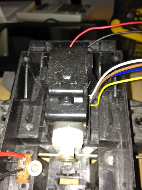
is the actual receiver he used. I could not have helped him otherwise. It is indeed a receiver from one of the many cheap RC cars that are available everywhere.
…that’s what I read in your post…LED’s are magic right
What I still want to add…in case the RC pilot drive the car in danger the Arduino could overtake and save the situation or the opposite…if the driver not like the skills of the Arduino he can just override it…
Got the VW Beetle for about 10US$, imagine…remote, car, battery charger and this all for 10 bucks…including a H-bridge on the receiver…aaaand it has a lot of lights…will see if i can make a project.
Got the chance to check the controller output of my VW Beetle with an oscilloscope and got all I need. forward, backward, turn left, turn right, blink left, blink right, start engine, horn and even the analog output for the speaker…
Will try to use them all on an autonoumus Beetle or a wall racer with some extra functions ;-)))
I want to just controll the functions through microcontroller on the RC reciever whereby its system run on its 9.6V battery comes along. I dont want that the Microcontroller burns in process where the reverse volts gets from the battery operated reciever to the micro controller. is it possible?
I want to use microcontroller to give a very basic automated function to this car which use sensors for movement.
My concern are :
1) if i connect the Sm6135W to Mega2560 would it work ? Like as per your tutorial above.
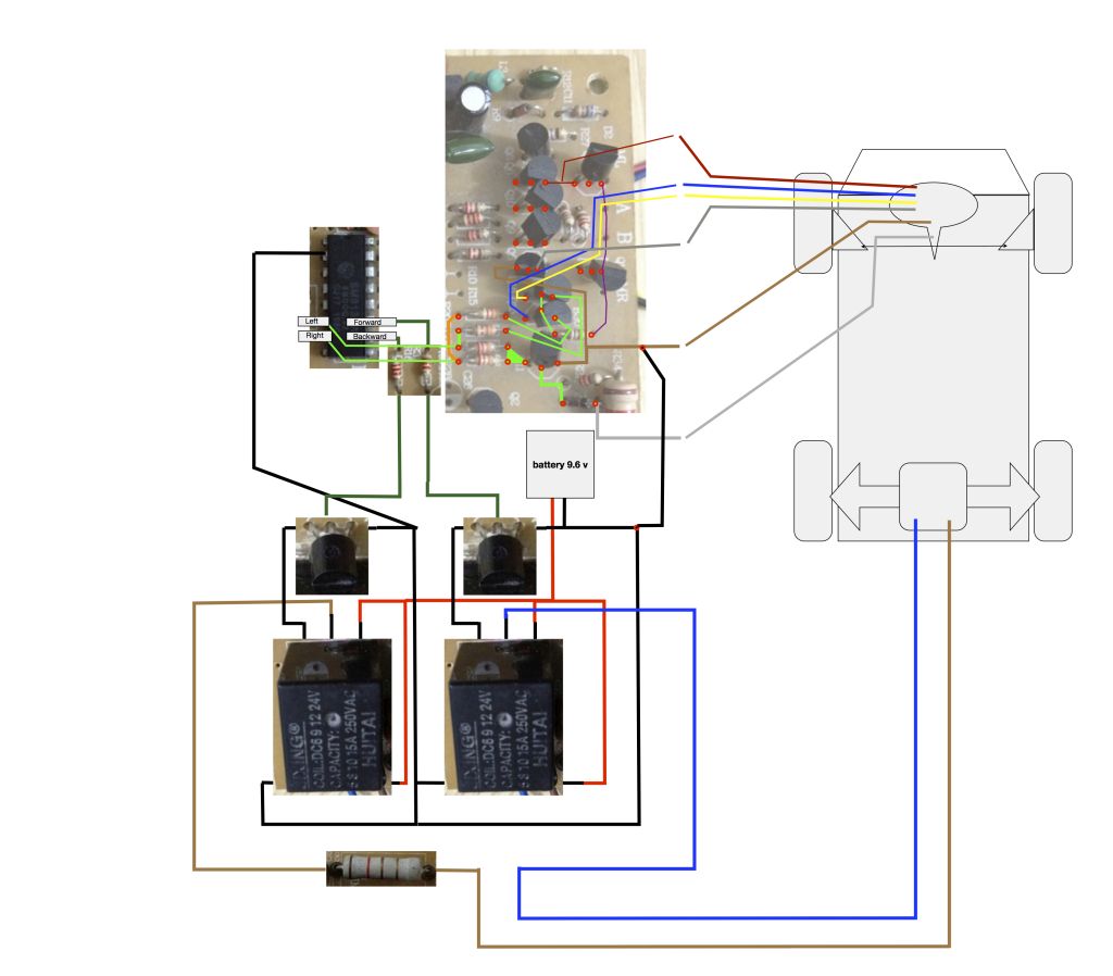
2) The Car use 9.6V from Ni Cad battery i.e " 1.2V X 8pcs in serial " how can i just give controll from microcontroller to the SM6135W without getting reverse volt.
3) Can i use seperate Powersupply for the microcontroller and let the Car use its traditional 9.6V battery powersupply?
4) can anyone suggest what are these relay for in this circuit? and was it necessary in this circuit?
please let me now if i confuse with anypart. i am new into this and very much interested.
A few questions Wouldn’t there need to be two wires soldered for forwards,backward etc each ? Also would you be limited to having the number of motors your rc car had ? And Is your code for a skid steer rc tank or what?
Thanks
Harry
is based on the common RF chip pairs that have 5 functions. If you look at the data sheet you will see the receiver chip has 5 pins labeled forward, reverse, left, right, turbo. With the turbo button enabled, you could make use of the other 4 pins to control other devices. The sketch he provided doesn’t offer any steering/driving what so ever. The coding to make a machine move would be up to you.


 but I prefer controlling more than just motors
