

Need more time…
…since other things also need my attention 
I am voting for a 36 hours day… hahaha…who will agree to this???
Need more time…
…since other things also need my attention
I am voting for a 36 hours day… hahaha…who will agree to this???
all I can say is : ALL THE
all I can say is : ALL THE BEST BRO! 
RC Receiver Hack
Hi. i am wondering if this can be achieved.
I want to just controll the functions through microcontroller on the RC reciever whereby its system run on its 9.6V battery comes along. I dont want that the Microcontroller burns in process where the reverse volts gets from the battery operated reciever to the micro controller. is it possible?
sorry but I cannot
sorry but I cannot understand what exactly what you are trying to achieve, can you be a bit more clear?
SM6135W Chip & Mega 2560 Micro controller
Hi, I was wondering if i can make mr RC car complete Automated !!
what i have.
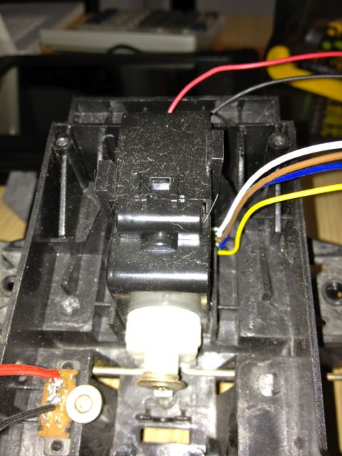
1) RC Reciever Controller : http://i1265.photobucket.com/albums/jj519/soni991/RC%20Car/IMG_6670.jpg
2) Steering Wheel Motor: http://i1265.photobucket.com/albums/jj519/soni991/RC%20Car/IMG_6672.jpg
3) Back Side Motor : http://i1265.photobucket.com/albums/jj519/soni991/RC%20Car/IMG_6673.jpg
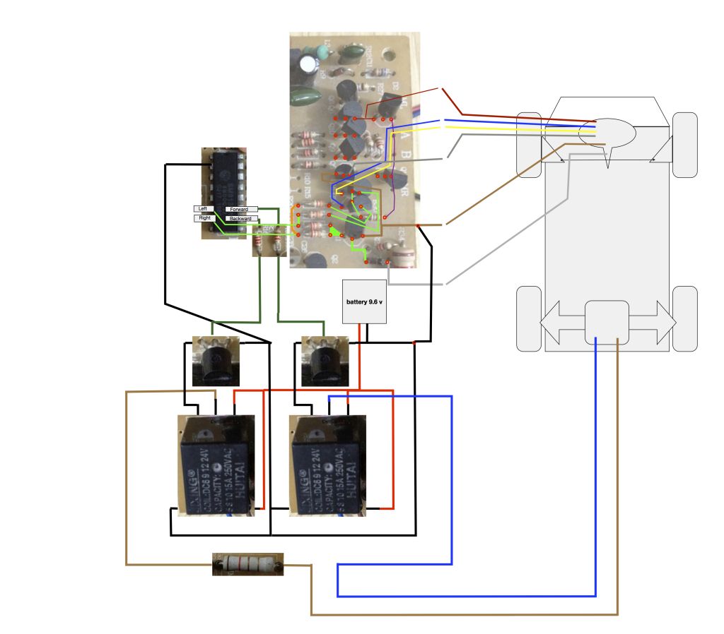
4) Schematics of my RC Board i figured out : http://i1265.photobucket.com/albums/jj519/soni991/RC%20Car/RCCarschematics.jpg
I want to use microcontroller to give a very basic automated function to this car which use sensors for movement.
My concern are :
1) if i connect the Sm6135W to Mega2560 would it work ? Like as per your tutorial above.
2) The Car use 9.6V from Ni Cad battery i.e " 1.2V X 8pcs in serial " how can i just give controll from microcontroller to the SM6135W without getting reverse volt.
3) Can i use seperate Powersupply for the microcontroller and let the Car use its traditional 9.6V battery powersupply?
4) can anyone suggest what are these relay for in this circuit? and was it necessary in this circuit?
please let me now if i confuse with anypart. i am new into this and very much interested.
I think this is your best
I think this is your best reference:
How to make a Wall Racer by fritsl
All the best
A few questions
Wouldn’t there need to be two wires soldered for forwards,backward etc each ? Also would you be limited to having the number of motors your rc car had ? And Is your code for a skid steer rc tank or what?
Thanks
Harry
The hack he shows here
is based on the common RF chip pairs that have 5 functions. If you look at the data sheet you will see the receiver chip has 5 pins labeled forward, reverse, left, right, turbo. With the turbo button enabled, you could make use of the other 4 pins to control other devices. The sketch he provided doesn’t offer any steering/driving what so ever. The coding to make a machine move would be up to you.
hi…i wanna ask…i have
hi…i wanna ask…i have try this project, but when i pull forward at Remote control, n then i touched the yellow wire to the solderpoint, LED only blinking. There is no response as it turn off/not glow. I use RX-2 chip. The LED only turn off even there is no send signal from TX at the pin of TURBO, RDB and LDB.
as i use this code, then supposedly the result will come out which the LED turn off when yellow wire touch forward solderpoint right?

then i don't know how to test the pin function before solder with wire for Forward, backward, left and right as the LED only blinking...
can u help me to make it clear for this situation.. thanks~
ok, so what I want you to do
ok, so what I want you to do is ask someone to keep the forward trigger pushed, while you run the code and move the yellow wire to different solder points until you get the LED to stay lit up.