Raspberry Pi Robot Arm with simple Computer Vision

A small Raspberry Pi robot arm I made over the past few month.

The robot arm is made of: 

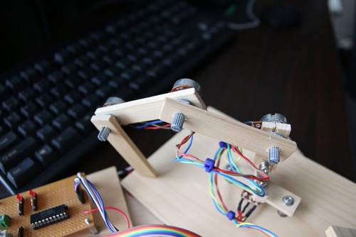
·         4 Dynamixel AX-12A servos

·         1 Raspberry Pi 2 model B

·         1 Raspberry Pi camera module

·         1 Electromagnet on the top

·         Aluminum, wood

·         A small circuit for communicating with the servos (see here for more info’s)

·         Colorful ribbon cables 


The Robot is able to search for screws (image processing with the Raspberry Pi camera module), pick them up and put them somewhere. Things I tried to optimize while building the thing:

1.     Make it move as smooth as possible

2.     Make it pick up the screws as consistent as possible


I wasn't satisfied with the servos moving around when given just the goal position. The stopping and starting was too harsh, too sudden. The robot arm was shaking after reaching it's goal position. I tried to fix this by implementing a software start-stop controller. Given a goal position, it makes sure that both the start and stops are shaped in the form of a sinewave. This means, that the motor would start fast, but slow down as it reaches it's goal speed. The same goes for stopping. The robot arm slows down fast at first, but slowly in the end. This was supposed to make it move more elegant, more smoothly. And to a certain degree, it works well.

The second thing worth mentioning is the Image Processing. I didn’t use OpenCV. The image processing algorithms applied here are all very simple. I wanted to write them by my own. An important library which I used was pythons "picamera". "picamera" provides an easy way to get greyscale pixel data from the Raspberry Pi camera module. The pixeldata then was put through some algorithms: Edge Detection, Binarization, Pixel Expansion, Labeling and Object Extraction. After that, the robot knows the positions of the objects in front of him (only in the x-y plane though). and it's area in pixels. It won't try to pick up an object if it's too small.

Here's the source code: screwPicker @ GitHub 

Some words to the 3 videos I embedded:

1.     The first video shows the robot searching for screws and other things and picking them up. In the second half of the video, I tried to convey how the robot sees the things.

2.     The second video shows the robot picking up a small "mountain of metallic things". Notice that the robot thinks the mountain is one big object most of the time. It tries to pick it up and after putting it somewhere it checks if there is something left and then starts over again.

3.     The last video is the oldest one. In it you can see how I tried to teach it positions with a small wooden replica arm. Note that there's no camera on the robot arm at the time.

Looks for screws and picks them up

  • CPU: Raspberry Pi 2
  • Operating system: Linux
  • Power source: 12v
  • Programming language: Python
  • Sensors / input devices: Raspberry Pi camera module
  • Target environment: indoor

This is a companion discussion topic for the original entry at https://community.robotshop.com/robots/show/raspberry-pi-robot-arm-with-simple-computer-vision

Nice arm

Very cool project!

I like the fact that you implemented a sinewave pattern for acceleration. Servo are often doing brutal movements and your arm movement are much more elegant.

I was quite surprised in your last video however, why is there such a lag between your movements and the movement of your robot? The PI CPU is a powerhouse compared to an Arduino so I don’t understand why the arm doesn’t follow your movements in real time.

I like your project and I’m curious, I might take an evening to peek into your code to see how you made it. :o)

Lag in movement in the 3. video

Hello Drake,

You are of course right. The Raspberry Pi is a powerhouse and even I must admit that I probably should have done the position following in real time.

Here however is the reason, why I at the time considered this the best solution: I remember doing the following in real time. The movement was quite shaky and I didn’t like it. I wanted to use the sinewave start/stop controller. But the thing only works if there’s a fixed goal position. So the way the arm following works is that the joints wont except a new goal position until they reach their current goal position. Another thing I noticed was, that there can be a lot of shaking going on when all the joints move at the same time. It looked a bit clumsy sometimes. That’s why I decided that the joints should move one after another.

The result was acceptable movement, from the viewpoint of elegance. But with a lot of lag. I probably should have rewritten the controller… But you know how it is when hacking around on robots… Sometimes, other things seem more important; At the time I was all about getting a camera hooked on the thing and finally start with the Image processing algorithms. ^^

That make sense

That make sense. :slight_smile:

Especially if we consider this step as a transition to the camera processing (when the robot knows exactly it’s destination)

Awesome!

great project buddy - can’t wait to see how it develops!

Nice design

You did a great job on the smooth movement of the servos.  That is hard to do.

That is cool you did your own video processing stuff.  OpenCV makes it a lot easier.

Thanks for sharing.

Regards,

Bill

smooth movement of the servos

Hello Bill, Thanks for the comment!

The smooth movement actually wasn’t that hard to do. The reason beeing that I used Dynamixel servos, which provide an easy way to control not only the goal position, but also the current speed! 

further development

Hello craighisset,

Thanks for the comment. I’m actually not sure if there will be a “next step” for this project. At the Moment I’m giving the ancient quest of “making a Servo from a geared motor” a try. ^^

Construction details

A super project!.

As someone who has no mechanical skills do you have any construction details?


Many thanks


BD

Construction details

Hello BD,

The construction is quite simple. Just go to the DIY center of your choice and buy some aluminium profiles. Some kind of quadratic profiles will do the job. Then you need a drill. And 4 Dynamixel AX-12As. Just drill some holes in such a way, that you can screw the profiles on the Dynamixels. The rotating part of the Dynamixel servo has 4 M2.5 (or M2 I’m not sure anymore) holes on it. just screw the aluminium profile on it and you’ll get the same thing I’ve done (or maybe even better, depending on how much time you spend on polishing the thing!). the profile should be about 12 cm long. I remember shorting at least one a little bit more because the servos reached their limits when doing some certain postures.

-Nekojiru 

Can you expand on how you

Can you expand on how you smoothed the movement? In laymens terms? How can I reproduce or learn from your code to implement the same smoothing in my own dynamixel motors?

Hey!

Hello Memmerich,

I am really sorry for the super late answer:

The Smoothing is actually quite simple and I am sure there are plenty of better ways to do it. First, we need to keep in mind that the servos in this project are Dynamixel AX-12A servos. But since you also got some Dynamixels, this should be clear enough. The Dynamixels are controlled via a serial protocol. One of the parameters which can be set over the bus is  the speed. This comes in really handy. Another big advantage of Smart Servos is that you can get the current position. Now all you have to do is to set a goal position. calculate some ramps for starting and stopping. and then, while resetting the speed and checking the current position in really fast succession, ramp up and down until you reach the goal position.

something like this:
1. Set Goalposition on Dynamixel
2. Calculate ramps (how many millisecs should the acceleration/deaccelation be?)
3. ramp up the Speed according to calculated tables (for example, if 10 ms have passed since start, the speed should be 10 or something like that) This is easiest if you are doing linear ramps.
4. also calculate the position after which the deramping should start.
5. after ramp up, the servo should move at some max speed.
6. after reaching the down ramp start value (some position), start the downramping of the speed.

As mentioned before, checking for position and resetting of speed parameter need to be done fast. Set the baud rate to some high value. I think I used 115200 as baudrate. query the servos as fast as every 10ms. I don’t remember how fast I did it. Experiment! 

Thanks for the responsein

Thanks for the response

in https://github.com/T-Kuhn/ScrewPicker/blob/master/servoHandler.py what is “rampTime”, and what value did you set for it?

Hey

I think it was about 20 ms. maybe I made it dynamic. I forgot. It’s the value (in millisecs) for how long the acceleration/deacceleration should be. 

Hello, sir
I am interested

Hello, sir
I am interested for robotic pack, if there is source code and the stages of the process. thank you

reply Report Spam

Hello, sir
I am interested for robotic pack, if there is source code and the stages of the process. thank you

**Potentiometer mounting on wood. **

Cool project!

What did you use to attach the potentiometer shaft to the wood pieces? I have been looking for various solutions, but they seem either expensive or a bit unstable/cumbersome.

** Hey there!Sorry for the**

Hey there!
Sorry for the late answer. I actually just sticked the potentiometers into the wood. Like this:

IMG_3297_.jpg

1 Like

Hello!Here’s the source

Hello!

Here’s the source code: https://github.com/T-Kuhn/ScrewPicker

1 Like

Sir can you plz give me those circuit diagram …plz