This is a 6 Wheeled Drive Robot Rover it is 18" Long 9" wide 15" wide if you count the wheels And 8" High it is powered by a Raspberry Pi with 3 L298N Motor Drivers and a Adafruit servo Hat . It is Controlled with a wireless keyboard or autonomous with a HC-SR04 ultrasonic Distance sensor or a light Follower sensor module. it has a web cam with streaming video and motion detection via CpenCV.It also has numerous sensors including A ADS1115 analog to digital converter, MPU-6050 accelerometer, HMC5883L digital Compass. DHT-11 digital temperature and humidity sensor and a BMP280 barometric pressure and altitude sensor. I'm in the Process of building a custom pan tilt unit with High torque servos that ca
n handle the weight of my web cam and I am working with voice recognition for verbal control. In the near future will be adding a GPS module.
Many people think you have to use a Aduino with the Raspberry Pi to do the simple and continuous work but the Raspberry Pi can do everything that a arduino can do and more, but since the Raspberry Pi has no analog pins a analog to digital converter is required. The arduino is a great Micro-controller. but with the Raspberry Pi you can write one program that will combine all of the features that you want for a complex robot.
I first started out building Arduino Robots. But after I built a few of them there was little challenge left. So now I strictly use the Raspberry Pi. I like the fact that you can have the robot take verbal commands and says preprogrammed responses.And
with the Raspberry Pi camera module or web cam you can make it see,that is one thing that the Arduino do. It just does not have the resources to do video.
the Robot is controlled with 3 L298N Motor controllers and I had to use 6 , 313 RPM HD Premium Planetary Gear Motors.
.I tried to use standard motors but they did not have enough torque to turn the Robot. I ran just fine going foward and reverse but could not turn with the standard motors. the motors I chose have 4X the Torque as the Standard Motors.
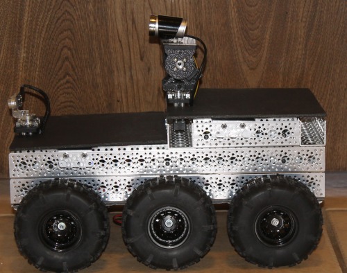
Side View Second Stage
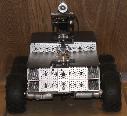
Front View Second Stage
Right now i'm in the Process of designing and Building a 4DOF Robotic Arm I want to Install quick disconect latches so I can make it easy to take on and off.
Obstacle Avoidance Via Ultrasonic sensor and Remote Controll Via Web App and Wireless Keyboard Control.
- Actuators / output devices: 313 RPM HD Premium Planetary Gear Motors
- Control method: Autonomous and remote controlled
- CPU: Raspberry Pi 3B
- Operating system: Raspbian
- Power source: 14.8V Li-ion
- Programming language: C++, C, Python
- Sensors / input devices: GPS, HC-SR04 Ultrasonic distance sensor
- Target environment: outdoor, The Moon Mars Rover
This is a companion discussion topic for the original entry at https://community.robotshop.com/robots/show/raspberry-pi-6-wheel-drive-rover
This looks really sturdy.
This looks really sturdy. Would be interesting to see some video of it running or maybe tackling sme obstacles!!!
Interesting using an ADC in place of an arduino. The reason I use Arduino as an ADC is because of the cheapness and availability of documentation and ease of programming. Much better to do it ‘direct’ though.
ADC
The ADC was only 9.00 USD so it was just as cheap as a Arduino clone. The ADC uses the I2C protocol and since I have 3 I2C sensors it was real easy to setup and program.
Video
I will make a video in the near future. Since I do not have a video camera or any one to take the video while I control it or using obstical avoidance. I will have to use my DSLR Camera on a tripod with a long Lens to take the video and that is a bit of over kill just to take a short video.
More information please?
I love this robot. Seems too expensive esspecially with the number of actobotics parts for me too build but doesn’t mean I wish I had the budget to build it lol. Nice robot!!! I want one in my home for me to program. Could you post pictures of how your robot works or at least the build process? Thanks!!!
At First I started with one
At First I started with one layer of the actobotics frame and I had 8 motors that I had laying around and added two sets of tracks on each side but that did not work well for me so i changed to 6 wheels and I have building it up a little at a time each month. I did not have the budget to do it all at once either
Nice chassis
Hi Wildwingman,
I like the Actobotics chassis you have made. I’m a big fan of the actobotics line, and use it a lot on my bots. For what it saves you in work and the quaulity, it’s really worth the money.
I am assuming this will be an out-of-doors bot. What voltage are you running the motors at?
With the L298, there is a voltage drop of @ 2v at lower currents and can get near 4v+ at higher ones. The L298 also has a max non-continuous current of @3amps. Those motors have a big stall current of 20amps or so. You can in theory run very close to stall current in just general use. You may want to look at other options for driving the motors, but I understand that the L298 is a very inexpensive solution and I use it some as well on smaller bots.
Nice bot!
Scott
I’m running at 14.8v, 4@
I’m running at 14.8v, 4@ 3.7v BRC 18650 Li-Ion Batteries on each motor controller. I tried using 2 Adafruit motor Hats but they could not handle the amp pull and were over heating. This thing is really fast and will go over 20mph.
I would love to try it at one of those ATV obsticle course competitions. Using the GPS I think it would do well. But since they do not have anything like that around here and I can’t afford to go to Colerado for the Sparkfun competition it is kind of a pipe dream.
Regarding the difficulty
Regarding the difficulty turning, you might consider slightly lowering the two middle wheels. Lowering them by perhaps 5mm might make a huge difference in its ability to turn/rotate.
**313 Planetary Gear Motor Circuit. **
You said the 313 Planetary Gear Motors used the L298N motor controllers to the Raspberry Pi. That makes sense, however, the max current for the motor controllers for the L298N is 2A and I would assume your robot is taking more current than that 2A because the motor’s stall current is at 10A. I was wondering what power supply you are using for those motors and the circuit diagram (if you are giving the motor more than 2 amps through the motor controller). I am in the same situation where I am trying to power the 313 planetary gear motor off the pi but I am worried that I might burn the L298N motor controller because the current rating is really high.

