

What is it?
This is a quick mockup used to test the IR obstacle detection circuit which came out of this forum topic:
https://www.robotshop.com/letsmakerobots/node/17316
It uses this circuit:
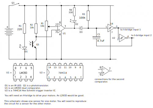
In the forum topic I mention the problems using a 1 Meg resistor in the delay components caused. Switching to 100k solved them, but the real solution was attaching one end of the delay capacitor to the second inverter, as you see above. This provides positive feedback which forces the capacitor to reset at the end of the delay. If you need to use a 1 Meg resistor for a longer delay, with this configuration it is ok.
At the moment it uses this h-bridge:
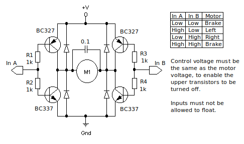
but I intend to trial a couple of changes with an L293D. It is powered by four AA batteries.
Method:
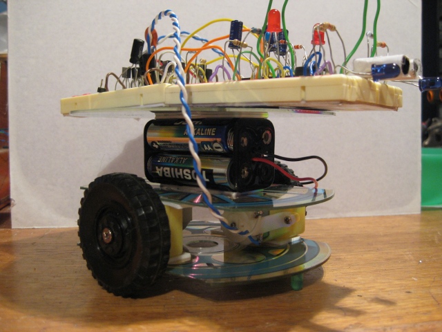
I got it together in around half an hour using a few old CDs and some double-sided tape. Most of that time was spent populating the breadboard!
It basically a multi-layer sandwich of a CD, some tape, motors, more tape, another CD, some tape, a battery pack, some tape, another CD, yet more tape, and a breadboard with components.
The circuit seems to work quite well, but would obviously benefit from better sensor placement. Possibly could do with lowering the value of the IR LED's resistor, too. Might try pulsing it at a low duty cycle and increase the LED current.
Anyway, it was a really quick and easy way to construct a mobile test-bed.
I used these motors:
http://www.altronics.com.au/index.asp?area=item&id=J0015
I used these phototransistors:
http://www.jaycar.com.au/productView.asp?ID=ZD1950&keywords=phototransistor&form=KEYWORD
Photos:

Note the old LEDs superglued to both ends of the undercarriage to act as skids.
https://www.youtube.com/watch?v=h3CShwF19vQ

