My camera does not do close up very well. But here it is anyway. The top portion is for two red led's I added and they are on a separate circuit.
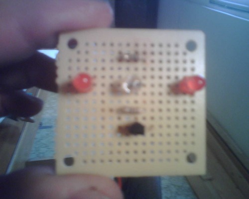
The resistor is a 1/4 330 and the transistor is a NPN Hfe 200 part number 276-1617 radio shack. Phottransistor is a t-1-3/4 it says the collector is the smaller wire on it and the emitter is the larger wire. That may be my issue. but I am not sure. I connected the emitter to the + cable on the resistor and the collector to the base of the tranistor.
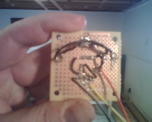
Red wire is for + black is for - and the yellow is the input wire.
The LED's work perfectly. The top resistor is for the LED's
*************************************************************
I am making this as pictured below.
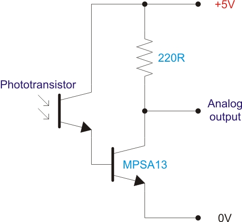
The MPSA13 I am substituting a transitor.
It has 3 pins. 1 = emitter, 2= base, 3 = collector. Now would I connect the phototransitor to the collector then the base to the ground 0V and the emitter to the + 5V?
Thanks for your help. :) I wish the transmitter instructions had the ground and voltage then I would definalty know. :) but I am learning.
help! 
My circuit seems to be working. But the phototransitor seems to have an issue. The longer pin on the phototranistor is the positive right? I have that connected to the resistor then connected to a + V pin on my picaxe. The - end I have connected to the base of the transistor. Then I have the emitter connected to a - or ground pin on my picaxe. I have the collector of my transitor connected to the resistor which I also have connected the output cable which is connected to the analog input pin of my picaxe. This seems to me the correct way to connect. There are no bridges that I can see.
When I disconnect the +v cable the debug goes down to 0 because it is not getting power. So that makes sense to me. The ground is working when I connect and disconnect it. And the output cable seems to be working when I disconnect it. That cable is connected with a jumper cable to the other end of the resistor.
So here is how I have the circuit setup. the phototranistor’s positive is connected by jumper cable to the one end of the resistor. Next that same end of the resistor is connected to the +V cable at the resistor. so on the same solder all three of those are connected ( jumper to +v long wire on the photoresistor to resistor and the V connector cable). I have the - short wire on the photo sensor connected to the base pin on the transistor with a jumper cable. Thats the only connection on the base pin of the transitor. Next I have pin 3 the collector pin connected only to the other end of the resistor with a jumper and the output cable analog is connected there also at the transistor. On pin one the emitter pin of the transistor I have only the - negative (ground) cable connected then connected to a picaxe ground.
Like I said when I test the cables it seems to work. Now I do not have the IR LED’s connected yet but I should get a better reading than what I am getting I would think.
When I do the code: main:
readadc 1, b1
debug b1
goto main
It does nothing but fluxuate like crazy. Could it be working correctly? If I disconnect the + cable it goes to 0. If I disconnect the ground it stays around the same fluxuation. If I disconnect the input cable it still fluxuates weirdly. I am getting some IR LED’s tomorrow. Should I just start over? It seems to me my circuit is correct and working but the debug is just weird fluxuations. Or instead of connecting the jumpter from the + of the phototranisitor with a jumper to the resistor and the + cable there also. Maybe I should just make a jumper from the resistor to the + connection cable? In my mind this should work but maybe not. I am still just learning. I may be wrong as far as the + wire of the phototransistor being the longer cable because of LED’s. I dont know. It seems to work but the freaking fluxuations are all over the place.
Thanks for the help.
ok
Now when light is on the sensor shouldnt the value of my code for b1 go up? and go lower for less light? I tried connecting up the ground - pin on a phototransistor to a 1k resistor. I have the output cable directly coming from that pin without going through the resistor and I have a direct connection to my voltage on the + longer wire on the photo resistor. I am working with only 4.5 volts so I am going to try without a resistor at all and see what happens.
this is weird
Now I get fluxuations on those analog pins without it even being connected on the pixaxe board. Should that happen?


