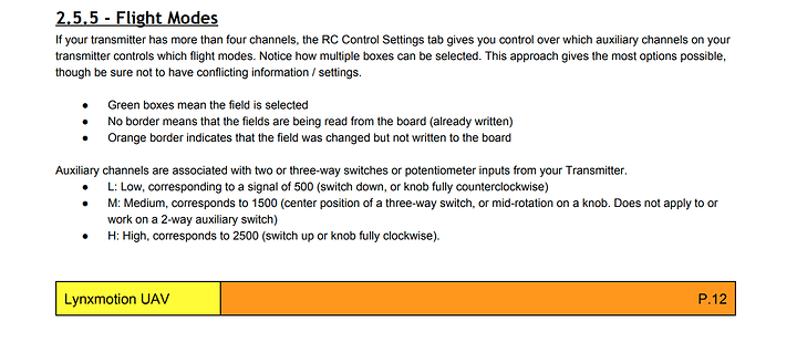
I have a quadrino nano now communicating with an frsky receiver through an inverter. I can see all of the channels changing in the Live RC Data readout, and I’m able to control motors. I have adjusted my endpoints to range from 1000 to 2000, but I can’t adjust a Min to 500 or a max to 2500 as it indicates on p.12 of the user guide. However, I have a couple of follow up questions about other issues.
When I set Arm, Horizontal, and other modes with the auxiliary port green boxes and try to Write Settings, I’m getting no change to the orange border around the green boxes, indicating that the setting didn’t transfer. The leds are illuminating indicating that transfer is taking place, but my auxiliary switches are not working for either Arm or Mode settings. I read somewhere that it was necessary to wire the auxiliary port to a “Mode Pin” but I’m unable to find a pin that is labelled “mode.” Was that for a previous version of quadrino, or is there something I’m missing? If I am using serial port 3 for sbus communication, is it even possible to wire an auxiliary port? Are the radio pins input/output, or just input? Do auxiliary ports require 500 for a LOW and 2500 for a high, or can i get by with 800 for a min and 2200 for a high?
Thanks!
I’ll have to check the manual regarding the values or 500 to 2500 as this doesn’t make sense.
Signals should be between 1000 and 2000 even for AUX inputs.
Are you using MultiWiiConf or WinGUI ?
I would greatly suggest to use WinGUI for the following as it’s less buggy.
In your “Flight Deck” you have the “Aux1 / Aux2 / Aux3 / Aux4” displayed.
When you move your switches on your transmitter, are the changing the values of those Aux inputs ?
Once you can move a switch and see the result on the Flight Deck then you can move to the RC Control Settings tab.
Orange square mean a change that has not been saved, as soon as you save it’s gone. (WinGUI)
Let me know from there and we can move further if you need help.

Here’s a video of what I described in my previous message. Also, i’ve included a screenshot of the section in the manual I mentioned. Thanks!
Switch seems to be set right for a (L / M / H) on Aux2 and i guess your Aux1 is working since you are trying to set it in the RC Control Settings tab.
I see the issue of the settings not saving.
Have you tried to click the “Read” prior or after that ?
Aux above 4 doesn’t seems to be possible:
Regarding the numbers, the real way to write it would have been:
- L: Low, corresponding to a signal around 1000
- M: Medium correspond to 1500
- H: High correxpond to around 2000
Yes, I’ve tried to Read as well and nothing happens.
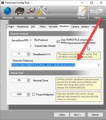
As for the Receiver settings, I’m using SBUS, so the Channel ordering is greyed out when I change the Rx Protocol.
Am I the only one having these issues?
I’ve not seen anyone in this specific case, no.
In the background i see Arduino IDE open, how did you load the code at the end ? (FCT or Arduino)
Since you are familiar with Arduino IDE i would try to wipe the EEPROM with THIS example then use FCT to get MultiWii flashed.
That seems to have made the difference. I now have the ability to write settings. Thanks! I had arduino open so I could look at the config. I’m considering writing some auto code for this if possible. However, I had never written to it via arduino up until this point.
Good news
The settings are saved in the EEPROM and sometimes they get bad values when “flashed” but it’s the first time i see one that cannot be written. This would have cleared all values so you will be good from now on.


