

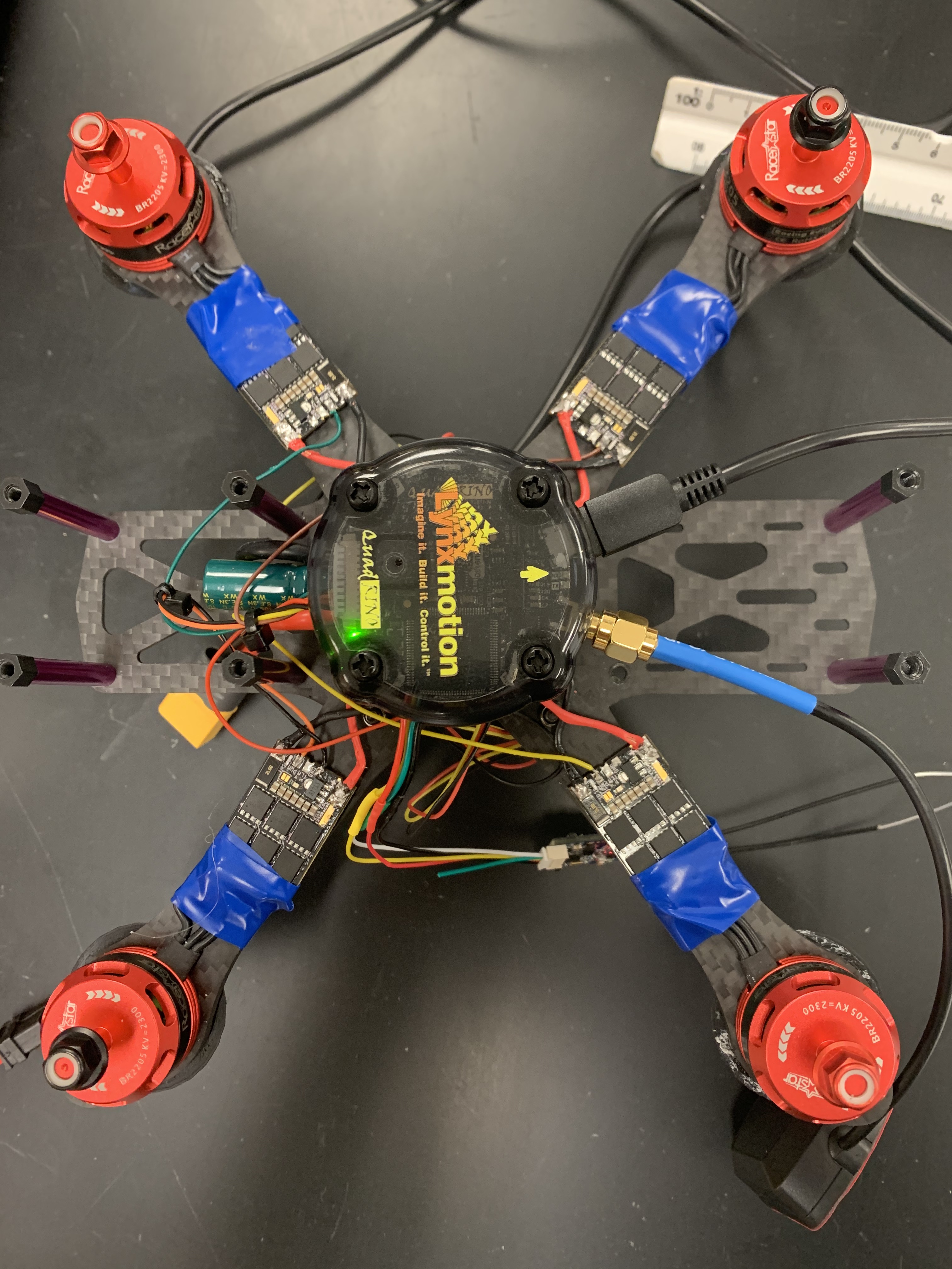
I’m working on setting up a quadrino nano drone and am having some issues. The first thing I did after ESCs were hooked up (after smoke testing) was run the Arduino Raw Sensor Value Tutorial. I received signals from all sensors with the exception of GPS. I then got the FCT set up on my Windows machine, set up the drone as I have it, and flashed the firmware. I opened the MultiWii Config to begin that process of setup and my sensor values were all over the place, even with the drone sitting stationary on my table. I tried to calibrate the accelerometer and magnetometer based on the written directions in the manual, but never saw any change to GUI while rotating the drone. I left for lunch, came back, and now the FCT won’t even recognize it. I get a build error when I try this which it wants me to email to FlyingEinstein. I’m also not seeing the same lights I did previously. Any help you have is appreciated. Thanks! Attached is an image of the drone I’m building btw.IMG_1122|345x460
Hi gwpierson,
There seems to be multiple issues at the same time.
You loaded the code via Arduino IDE for the Raw sensor value and it worked, then you used the FCT to load the correct firmware and it also worked but you had issues in the GUI.
I’m suggesting to use WinGUI instead, it’s a much better interface with less bugs.
Now you cannot load anything to it, either Arduino IDE or FCT ?
Also, when you only power the board by USB is it powering up ?
When I load from Arduino IDE, I receive the message that the upload completed. However, when I open the serial monitor and try to read sensor values, nothing happens. The board seems to be powering up, but the only light that illuminates is the green light next to the motors connector.
Ok - If it’s uploading it mean the board is powered.
Can you provide some screenshots of the issue in the FCT ? You might want to create a new profile and load it without changes for a try.
Ok, the upload was successful. No issues with the FCT this time, with a new profile and all default settings. I opened the WinGUI to test sensor values. Calibrate ACC showed a slight change in the vertical speed. Calibrate Mag showed a slight change in heading, but only briefly. I’m definitely getting more lights than I was previously. However, when I rotate the drone in any direction, I’m not seeing any change to the readings on Flight Deck.
That’s a good news.
Try to do the calibration as explained here
Done. Still not seeing any changes in the Flight Deck.
Can you upload a video to YouTube showing what’s happening ?
It’s important to do the calibration and move the Quadrino Nano just like the GIFs in the tutorial while doing it.
Video is private, cannot access it.
Sorry. Try again.
still not working
Argh. Youtube has a save button for settings. Apologies again. Should be available now.
Nice video, you seems to be doing everything right.
Can i ask you what have you choose as the “board” in the FCT software ?
If you can send me the profile by clicking the blue text “explore profiles on disk” ? Just Zip it and attach it here.
I see on WinGUI the “I²C Error count:” being increasing a lot, this should be at “0” all the time.
It means that there are sensor communication errors.
On the “Sensor Graph” tab you should be seeing each sensors values, can you have a look and tell me which one don’t have values ?
Board is Model Nano, version V1. I zipped all of the profiles. Test is the one I was using this morning in the video.
As for the sensor graph, the z shows up right at the beginning as an almost vertical line upwards. But that is the only one that shows up. All are checked in the selection boxes on the right.
Profiles.zip (568.1 KB)
If you don’t mind, i would ask you to do one more test.
Use the Arduino IDE to load the “BLINK” basic example to the board. Then re-flash using the FCT.
My worry is knowing what happened.
Since the board do not seems to have sensor communication, but it was at first when you tested i figure something happened.
We can replace the PCB of the Quadrino Nano but i don’t want you to end up in the same situation after the replacement
Ok. Orange LED is blinking.
Re-flashed with the FCT. Worked fine.
Still no sensor response after flash.
Directions state to power 5V from the ESCs, but I don’t have 5V out on ESCs, so I pulled 5V directly from PDB. That shouldn’t matter, right?
I don’t have a clear view of the wiring on the image you posted.
Can you provide a better one?
If you powered from an external source, it’s important that it was 5v but also to properly connect this Gnd source to the board.
I’ll have to send that Monday. Have a great weekend and thanks for your help.