

Thought I would start a blog documenting my rostock build. Hopefully this will help some other noobs work out the minutae of a project involving so many disciplines!
This'll be my 1st CNC machine and my introduction to 3D printing. Before beginning this project I had never even seen a printed part aside from pictures and video. So it is a bit of a leap in faith! My experience in electronics is limited to about a year of fooling around with Arduino boards and AVR chips. Mostly involving experiments in motion control with motors, servos, steppers plus some shape memory alloy actuators. That along with a bunch of LED blinking :D
With the help of LMR I have recently started etching my own circuit boards and have dabbled in circuit design. With that I figured it was time to begin building the machine that introduced me to Arduino and microcontrollers in general. A RepRap!
Anyone not familiar with the RepRap Project should really read up on the history of the machines and the people who create them. It's fascinating stuff involving some real open source pioneers.There's kind of an ethos that goes along with the Arduino and RepRap projects and it's just friggin' smooth.
But that's zen, this is now and now was the time to choose.
When choosing which "species" of RepRap to build I did a lot of pondering and head scratching. Should I build a "Repstrap" fron an old printer? Purchase a pre-made machine? Build a proven design like a Mendel or MendelMax? Do I even have the skills to pull something this ambitious off?
Enter the ROSTOCK!
I had seen pictures of the machines plus some videos of them running and it looked like a really different breed of printer. I loved the way it moved and had such a roboty vibe but the fact that it was still kind of beta spooked me a bit. Thankfully a couple of members here at LMR were building them so I decided to join FrankNeon and Ossipee in their adventures!
SOME TIPS FROM A NOOB.
There are a lot of parts to one of these things. About a zillion little screws, bunches of printed parts, wires, pulleys, bearings, belts, motors, heaters, rods, gears, and other things. And that's just the mechanical parts! On top of that there is an Arduino Mega with a RAMPS shield running the whole show. Add the Arduino IDE experience to the fun plus some other necessary software and you're in for a good time! But you're gonna need parts.
The great thing about the whole RepRap project is that you can source all of your parts from anywhere and everywhere. Bills of materials are available and there is a plethora of auction site sellers more than willing to exchange a little cash for some goodies but choosing said goodies can be a challenge. Order the wrong part and you're stuck with it, plus you're gonna have to figure out what part you actually needed and order again. Since screwing up on the parts safari can cost both money and time and the fact that this is my FIRST EVER PRINTER I decided to let FrankNeon source my parts and send me a kit.
THE BUILD!
Most of the build has been pretty straight forward and I've been surprised at how easily things fit together but with any open source sauce there are some snags. The first hiccup was the pulleys:

Frank provided some really sweet gold anodized pulleys but the inside diameter was 3/16" and the motor shafts are 5 MM. Not a big deal but something to be aware of. I also screwed one of the pulleys up while drilling it out.
In case you decide to source your own stuff the pulleys are: Mxl and XL Series Timing-Belt Pulley 1/4" Belt Width, .635" OD, 18 Teeth. I got a replacement from Mcmaster Carr and it was about $10 :O so don't toast yer parts!. One thing to be aware of if using this pulley is that the hub where the set screw locates is pretty thin once drilled out. It doesn't seem to be a problem but you may want to use pulleys with a larger diameter hub.
SOME STUFF ABOUT MOTORS.

Both NEMA 17 motors. The big beefy one on the left is one of the motors that Frank provided. The little one came out of an old printer. Just be aware if you’re ordering parts. There are about a zillion different NEMA 17 frame motors with just as many different specifications!
DISREGARD THE FOLLOWING BECAUSE IT CAN BURN YOUR HOUSE DOWN AND MAKE YOUR FEET SMELL BAD!
Steppers are cool but a little complicated. 4 wires, 2 coils and if wired wrong can cause all kinds of grief !
With open source stuff you’re often somewhat alone but crowded at the same time. Lots of info scattered everywhere and most of it questionable but this seemed to work for me.
Schtepper Schematic:
I have the Bi-Polar shown on the right and they do seem to be the most common. It's been rumored that Uni-Polar motors can be used the same way but I have no experience with them. Pay no attention to the colors! I've fooled with a bunch of Bi-Polar motors and as far as I can tell the wire colors are just to make them seem festive or something.
There are plenty of tutorials on the net about figuring out which wires are which but the main task seems to be simply identifying which wire pairs connect to each coil. After that it's gravy baby!
The method I used was just to hold 2 of the motor wires together while spinning the motor by hand. When 2 wires connected to the same coil are held together while spinning the shaft some notchy resistance will be felt. That's it! now you have your 2 pairs!
THE PRECEEDING INFORMATION MAY BE BAD. IT COULD DESTROY YOUR REPRAP OR CAUSE YOUR SPLEEN TO SHOOT OUT OF YOUR RECTUM AND BURN YOUR UNDERPANTS!!!
A word about:
This was one of the confusing things to me when I started looking at building a RepRap. Ramps, this, Pololu that, Sanguinololu too! All pretty confusing to a noob! I guess the bottom line is that the Reprap project goes hand in hand with Arduino. The "brains" of these machines is basically an Arduino Mega or a variant of the Mega. RAMPS is the " RepRap Arduino Mega Pololu Shield" It's simply an Arduino shield that has all the goodies for driving your Reprap! The "Firmware" is a sketch (Damned complicated one) that runs the whole shebang.

I thought it was a little early in the build to be worried about the electronics but the motor plugs must be properly connected or else the motors will run backwards or stutter. Neither of which is good.
The cool thing about the way the steppers plug into RAMPS is the pinout. The male pins are labled well with the axis and extruder plug locations The 4 pins driving each motor have the (+) and (-) terminals for each motor coil divided up with one coil on the "inside" 2 pins and the other coil on the 2 "outside" pins. This allows the plug to simply be reversed to change motot direction!
I found my 2 pairs and hooked one pair to the 2 pins on the "outside" of the plug and connected the remaining 2 wires to the 2 center pins. I did this X4 for all the motors and proceeded to build
THIS:

The base assembly is pretty straight forward. FrankNeon supplied me with the wood (Or MDF) parts which moved things along nicely! There is a printable template available that aids in layout if you want to do your own wood. The 3 large printed parts on top of the base are the top mounts for the idler bearings and limit switches. Note the mounting locations for the limit switches. More on that later…
Underside of bottom assy:

Not much to see but it's probably a good idea to do all your soldering/shrinkwrapping before mounting the motors. You'll need a variety of 3 MM .bolts/screws for the project. The screws that hold the motor brackets to the wood are 4 MM and the screws that hold the motors to the brackets are 3 MM. I had trouble finding small metric bolts locally but FrankNeon and Ossipee helped take up the slack! Nothing more frustrating than having a tiny little screw hold up the entire operation :P
Once I had the base assembled I started on the top plate:

Sorry for the bad pic :( The limit switches are mounted on the inside of the printed parts and the idler bearings are mounted to 8 MM bolts. The limit swithhes are wired normally closed if you use the default in the Marlin firmware but this can be changed if you use normally open switches.. I opted for the default for simplicity. I picked up the limit switches from Radio Shack and they fit PERFECTLY. The only modification was drilling the holes in the switches out a bit for the 3 MM screws.
I was a little confused about how to put the idler bearings together. Seems some folks use washers on the outside of the belt but the wiki says that there is a slight angle built into the assembly to prevent the belts from slipping off. Mine are open which makes assembly and disassembly easier. I've done a bit of live testing and the belts seem to stay put fine. I did put some large fender washers on the back to keep the belts from rubbing on the printed parts.
Once the top and bottom assemblies are together I guess it's a good time to fool with the effector plate and the 6 articulated arms. I've seen pictures of several different arm setups but we went with these:

Sorry for the bad picture but it's important to maintain the 250 MM dimension from centerline to centerline of the holes in the rod ends. I drilled 2 holes 250 MM apart in a piece of sheet metal to align mine. The rods are 5 MM diameter carbon tubes from a store that sells RC plane parts. I think it's a bitchin' looking part with the carbon rods and silver ends! Only 5 to go...
Once the rods are built they are connected to the effector plate:

///
And to carriages like this:

///
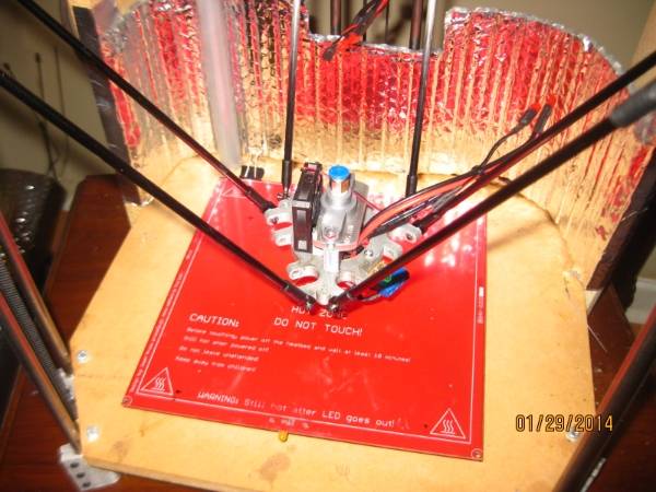
The construction of the Rostock is pretty straight forward and it's nice that all the mechanical bits are out in the open! An added nicety is the fact that the only wires in motion are the 2 heater resistor wires and a pair of small wires for the thermistor. Most other RepRap designs have the bed in motion but it remains stationary on the Rostock. This is my first printer but fidgeting with the bed can be a PITA but this design makes it very accessable.
I was surprised at the strength of the effector/arms assembly. It's still pretty rigid after running .5 kg of PLA and about .3 kg of ABS through it.
One of the things that confused me was the mounting of the hotend and the wiring to the thermistor and heater resistor. Some type of dual plug setup would probably be best but I didn't have any so I put mine together with a home made lug deal:

///
This was my first hot end mount:
///
The green LED is driven by PWM which controls the resistor/heater. I did it to be blingy but It's useful to see the heater cycling.
Another mystery was the fastening of the hot end to the effector plate. Frank provided me with a J-Head from hotends.com and an aluminum mounting plate. The J-Head has a groove in it which mates with a slot in the aluminum mount.I fastened the aluminum mount to the effector plate with a couple of bolts.
///
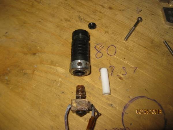
WHAT NOT TO DO TO HOT END!

Be careful when setting up the hot end! Make sure that the thermistor is in contact with the hot end and it may not be a bad idea to compare indicated temp with an IR themometer or something. I believe my thermistor slipped out of the hole and the heater tried it's damnest to make it hot! In the pic above you can see that the extruder pushed the brass part out of the plastic sleeve!
It can destroy itself if your not careful.
I figured I'd update this blog to show that I'm not just another casualty of the 3D printing revolution!
The hotend was repaired wirh some set-screws in the plastic part of the nozle and clicked along fine for quite a while before failing again.
Fixed again:
Just a steel sleeve around the barrel with some set screws. I sealed the threads with kapton tape and so far it isn't leaking.
Another problem that the Rostock has is the printed universal joints. It's a great design but doesn't hold up over a lot of use. I suppose it would be easy to print new joints and keep them handy but I decided to change to Traxxas rod ends made for RC cars.
I used part number 5525 which came in a set of 12 ends. I reused my 5mm graphite rods but had to drill out the rod ends for them to fit.
I did lose a little bit of build area because the arms are more constrained and can't reach the outer limits of the build plate.
Another change I made was going with 1/4" BSP to 4MM push connectors for the bowden tube. The nut-on-tube arrangement worked pretty well but was prone to popping off from time to time.
//
https://www.youtube.com/watch?v=OGWXkyn1KeA

