Problem with Lidar Lite v3

I want to confirm the findings discussed in this thread (robotshop.com/forum/problem-with-lidar-lite-v3-t16622) and ask some more questions.

I followed the instructions for the electrical hookup of the device using I2C (large capacitor and all). In my case, I am driving the device using a “micro” Arduino and I had to provide an independent 5V supply for the Lidar. I added the Garmin LIDARLite library to my Arduino IDE and ran Garmin’s example program GetDistanceI2C.

As the specifications say, I [size=1]saw[/size] reasonable (and roughly linear) distance reports from 1 m out to 7 m (the max I could obtain in my condo). Below 1 m, there was significant non-linearity, e.g., report 52 @ 50 actual, 35 @ 30, 20 @ 10. This seems reasonably consistent with the expectations from the specification and the behavior reported by others.

I am curious about the statement in this thread that “[font=Helvetica Neue, Helvetica, Arial, sans-serif][size=2][highlight=#ffffff]distances under 30 cm are not reliable[/highlight][/size][/font]”. While my admittedly sparse experience lends credence to the statement, I could not find anything in the specification or on the Garmin product page that supports it. Am I missing something official somewhere, or is the statement simply a result of lots of experience with the device?

Further, in an experiment with only two samples at any distance, the two samples were well within the accuracy range of each other, so I was hoping to derive an equation that would let me map reported distances below about 60 cm to the actual distance. So, does the “unreliable” statement mean that any measurements are bogus (e.g., non-linear in unpredictable ways) and non-repeatable so that my hope of doing the mapping will fail?

Thanks.

Hi,

Please find below answers to your questions and comments:

That sounds quite good! :slight_smile:

Indeed, as mentioned in the official specifications, the device is non-linear below 1 m (see instructions, page 2 under Performance). See below a screenshot of the relevant section:
LIDAR-Lite v3 - Specifications - Performance (manual, page 2, left-center).png

This statement comes from experience with the LIDAR-Lite v1/v2/v3. This was quickly noticed by our early customers and discussed with the manufacturer at the time (PulsedLight, which was later purchased by Garmin in January 2017). The rule of thumb of “under 30 cm” is related to how the optics involved in the sensor prevent the signal from being reliable at such short distances (when compared to the maximum, which is 4000 cm). That being said, distances under 100 cm (or 1 m) are still non-linear due to the sensor’s processing of the signal (and possibly the impact of the optics) and will be more variable due to reflectivity of the target and the surface’s shape and normal to the sensor than if it was further away.

See two answers above for the link concerning non-linearity in the official specifications from Garmin.

As mentioned above, while reflectivity of target, surface shape and target surface’s normal to the sensor always have an impact on distance measurement, this is especially important at short distances (< 100 cm). Therefore, it is possible that you could calibrate for these shorter distances (i.e.: create a map of readings/measurements vs true distance), but most likely this mapping/calibration will only be valid for those objects with that sensor specifically. Even further, it may only be valid in those lighting and weather (ok, condos do not typically have weather… :stuck_out_tongue: ) conditions, too. That being said, we are quite curious about what kind of results you can obtain. Indeed, non-linear does not imply not-consistent. This means you would need to determine all the variables that have an impact and account for them in your measurements.

This is quite an interesting idea and so we have contacted the manufacturer directly to obtain their opinion on this and how to best proceed. We will post here again once we have more info.

We hope the information above helps.

Sincerely,

The response was most helpful!

While I am just getting started with the device, I plan to do a lot of “calibration” because I have many different surface types and shapes in my environment (my condo): wood, metal, glass, stone, even people. Further, since I’m mounting the device on a pan/tilt mechanism attached to a wheeled rover, I’ll also have to deal with differing “aspects” (surface normals) with respect to the different surfaces. That said, I’ll be unlikely to investigate the impact of lighting, except accidentally.

I’ll gladly post any meaningful results from my experiences. I’ll also eagerly await any input you receive from the manufacturer.

Thanks.

Hi,

Here is some info concerning the non-linearity range of the sensor from the manufacturer:

[/font][/highlight]

Therefore, yes, it is doable. That being said, it won’t be simple but also not impossible, which is great news! :wink:

As they mentioned, you may also be interested instead in the [RB-Pli-17], which has multiple improvements including a much improved internal clock and temperature compensation, which leads to better signal generation and detection. They also reworked the entire signal processing bit so that is does much better at shorter ranges and for the entire range overall, too.

Let us know how your testing goes!

Sincerely,

I performed an extensive (but not complete) set of tests yesterday. I confirmed some expected behaviors, and also found some surprises.

I tested on many, but not all of, the surfaces found in the [size=2][font=Arial]area[/font][/size] where the rover will wander: fabric, stained/varnished wood, varnished wood, painted (light color) wood, glass, stainless steel, hot rolled steel (blued, waxed). I took readings at distances of 30, 50, 80, 100, 200, 300 cm, at angles of incidence (aspects) of 90, 45, 20 degrees. For each test I took as many as 200 readings and did sort of a mental average.

I have to disclose that the measurements of distance and angle cannot be considered precise. As a result the accuracy of some readings are a but questionable.

I’ll summarize the results here. I’d be happy to provide the details if I could figure out how to attach or upload images or a PDF.

][font=Arial][size=2]some combinations produced unstable readings; I categorized each combination as stable (where the individual readings varied by a few cm), unstable (where readings varied by as much as 10s of cm), very unstable (where readings varied by as much as 100s of cm); as an example the readings for stainless steel at [/size][/font][font=Arial][size=2]20° varied from 1 (presumably infinity) to over 300 cm[/size][/font]/:m]
][font=Arial][size=2]painted wood is the “best” surface and fabric the next “best” followed by any of the wood surfaces; glass and steel surfaces are bad news[/size][/font]/:m]
][size=2][font=Arial]90° readings are universally trustworthy (stable)[/font][/size]/:m]
][size=2][font=Arial]45° readings at distances >= 50 cm are trustworthy except for glass, steel, and stainless steel; the latter produce unstable or very unstable readings[/font][/size]/:m]
][size=2][font=Arial]20° readings between 50 and 200 cm are trustworthy except for glass, steel, and stainless steel; ditto[/font][/size]/:m]
][font=Arial][size=2]glass acts “opaque” at [/size][/font][font=Arial][size=2]90° but acts transparent at the other angles tested[/size][/font]/:m]
][font=Arial][size=2]for most surfaces, [/size][/font][font=Arial][size=2]20° readings @ 30 cm could not be obtained due to rover and room geometry [/size][/font]/:m]

These results have forced me to adjust my thinking about what I can achieve with the device. For the most part, it is not worth worrying about distances much below 50 cm. The non-linearity at and above 50 cm I’d seen in earlier tests is overwhelmed by other factors in my environment. As a consequence, I see no need (and as hypothesized by the manufacturer, no real ability) to construct a mapping that has any validity in my environment. I am also going to make sure that the glass is covered and so is not a factor, at least initially.

I am also going to have to adjust the expectations for using the device to create (and memorize) a map of the environment. Since angles much greater than [font=Arial][size=2]90° can be untrustworthy, I’ll have to move the rover more frequently and shorter distances so that I can achieve more readings taken at close to 90°. I think I should have expected this all along.[/size][/font]
[font=Arial][/font]
[font=Arial][size=2]I do have a couple of questions. Maybe RobotShop or the manufacturer can help:[/size][/font]

][font=Arial][size=2]as I said above, in some combinations, I got readings of 1 cm, clearly invalid; is 1 cm intended to mean infinity or error or something else?[/size][/font]/:m]
][font=Arial][size=2]the data sheet states a 680 microfarad capacitor should be used on the 5V supply; I’ve seen others use 1000 uf; I don’t have either of those values, so I used two 470 uf caps in parallel to give 940 uf; how close to 680 does the capacitance have to be? I’d really like to use only one 470 uf if possible [/size][/font]/:m]
][font=Arial][size=2]while I don’t anticipate buying the newer device for this project due to the rethinking above, I did do some searching, and it appears that the device is not yet available and in fact neither is a data sheet for it; when do you expect the device to become available?[/size][/font]/:m][font=Arial][size=2]
Thanks. [/size][/font]
[font=Arial][/font]
[font=Arial][/font]

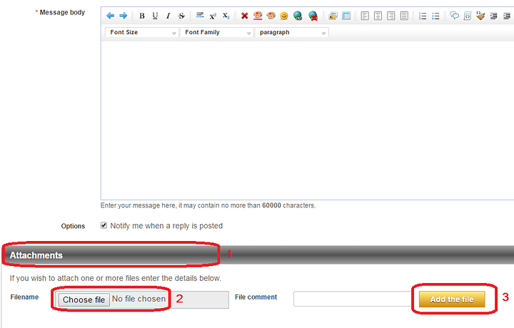
I’ll have a look in depth are your findings. To attach files, go in Full editor mode and use the attachment bar:

I have attached the full set of results.
lidar-results.pdf (37 KB)

Hey,

First of all, that is some nice results! Thanks for sharing this with us.

Lets first address your direct questions. Here are some answers to the following:

A 1 cm readings indicate loss of signal or an invalid reading.

If his power supply can handle the inrush current of the sensor, then the capacitor isn’t needed. We recommend the cap simply because most USB power sources will lock up if the device momentarily draws more current than the USB port can provide. Of course, in some situations the inrush current not been handled well by the power source could also cause brownouts to the other electronics relying on it, too.

The manufacturer should start shipping the LLV3HP by late January, so we most likely have inventory available by early to mid-February*. That being said, if you do choose to order some, we recommend you pre-order as early as you can so that your quantity gets reserved on the first shipment, since these may sell very quickly.

As we mentioned previously, reflectivity of the surface is quite important. Mirror-like surface and transparent surfaces will most likely give unreliable results in many cases, especially as you get further from the normal of the target’s surface. These results most likely hold true also for other optical sensors, since their beams will be affected similarly.
That being said, it may be possible to improve the results obtained with the LIDAR-Lite. Since the sensor uses a correlative signal processing approach, the longer you can integrate on a target, the greater the sensitivity and performance. The manufacturer recommends to change the measurement frequency to a lower value and increase the acquisition count for better performance.

As for the non-linearity at short range, the LLV3HP has this mostly corrected and it is quite possible some of those changes will make it to future batches of the LIDAR-Lite v3, too.

Something else worth mentioning is that you may want to take multiple measurements as you turn and move and see how well these correlate together to help determine their validity (such as values suddenly changing by multiple meters). Probability and statistics will be your friend at this point, especially when going towards SLAM algorithms and similar ideas.

We hope this helps!
Sincerely,

*: Please note this is still an estimate using the information we currently have available.

The response was most helpful, especially the last two thoughts. Thanks!

I thought it might be interesting to show the latest results from my LLV3 testing. I finished mounting the LLV3 onto a servo driven pan/tilt mechanism and modified the GetDistance sketch to drive the servo from 0 to 180 degrees (with 90 pointing “straight”). The sketch waits 500 ms after each servo movement and reads the LLV3. The sampling was done in my lab/office with the device mounted almost perpendicular/parallel to the walls.

I’ve [font=Arial]attached[/font] a plot of the results. The net result I think is even better than I’d hoped. The plot needs some explanation to be understood.

[size=2][font=Arial]The x and y axes show distance in cm from the lidar unit to the side and forward, respectively. The origin (red line) represents a 90° angle. The fuzzy green lines represent actual surfaces and the transparent colored rectangles identify the type of surface; blue is a cloth window shade, pink is wall, yellow is wood cabinet. The gaps in the green line represent actual gaps in surfaces; the short vertical gap on the left is that between the wall and a cabinet; the longer horizontal gap in the middle is an open door.[/font]
[font=Arial]The depiction of the environment on the whole is pretty remarkable. The scales must be taken with a bit of skepticism, unfortunately:[/font][/size]
][size=2][font=Arial]The shade (blue) is semi-transparent and in truth about 25 cm from the sensor; the reported distance is roughly in the high 30’s to mid 40’s.[/font] [/size]/:m]
][size=2][font=Arial]The first wall (pink) on the right is at about 45 cm and is reported about 52 cm. The second wall from the right is at about 65 cm and is reported about 65 cm. The third wall from the right is at about 65 cm and is reported about 70 cm. The fourth wall from the right is at about 350 cm and is reported about 354 cm.[/font] [/size]/:m]
][size=2][font=Arial]The first cabinet (yellow) from the left is at about 288 cm and is reported about 289 cm. The second cabinet from the left is at about 222 cm and is reported about 220 cm.[/font] [/size]/:m][size=2]These results seem [font=Arial]consistent with expectations. Distances less than 100 cm are “suspect” to begin with. Surfaces like the curtain would be tough in any case.[/font][/size]
[size=2][font=Arial][/font][/size]
[size=2][font=Arial]Overall, I am quite pleased.[/font][/size]

Hey,

Thanks for the update! This is pretty cool!

The results seem as expected: non-linearity under 100 cm (and therefore not exactly reliable) and great performance above that (such as your cabinets and far wall).

That being said, I’m still impressed with the results under 100 cm, especially with transparent material at an angle that is not perpendicular.

Let us know if you do more tests!

Sincerely,

P.-S.: The manufacturer does mention the non-linearity for the LLV3HP under 100 cm is much improved and the measurement accuracy across all distances will be better, too.