I got some digital line sensors. I am trying to do these steps:
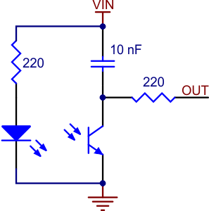
Set the I/O line to an output and drive it high Allow at least 10 us for the 10 nF capacitor to charge Make the I/O line an input (high impedance) Measure the time for the capacitor to discharge by waiting for the I/O line to go low
Here is my code currenly for testing.
main:
high portc 0 pause 10 low portc 0 pause 10 high portc 1 pause 10 low portc 1 pause 10 debug ' this draws out all variables to the editor.
goto main
And I do not see anything changing in the debug panel. I have searched on this site and used the ping node for this start to the code. But I dont think I am changing it back to input before putting it to low. I am looking over the Picaxe BASIC manual and am unable to find what I am looking for. Please help.
Here is the link to the type of line sensors I have. I have 2 of them. http://www.pololu.com/catalog/product/959
I do have them connected correctly and have double checked that. And I am using pin0 and pin1 for the digital inputs. :D
debug ’ this draws out all variables to the editor.
goto main
it is still 0. Maybe I am getting a time out error? This is in the picaxe manual and perhaps that is my issue?
Information: The pulsin command measures the length of a pulse. In no pulse occurs in the timeout period, the result will be 0. If state = 1 then a low to high transition starts the timing, if state = 0 a high to low transition starts the timing. Use the count command to count the number of pulses with a specified time period.
I just saw an error with my code. Changed it and still the same thing… I have a sensor on pin0 and pin1.
Does it matter if I have servos on? when I do the pulsin is that on the wrong pin maybe? for pin 0. Because when I do the pulsout on pin 0 my servo moves.
I was using digital pin 0 and 1 and with analog was using 1 and 2. And the voltage and ground were connected to the voltage right by the input pins for both analog and digital. And the grounds were on the grounds right by the 28x1 chip on the top of the board.
Pulldown resistors on the AXE020 board from the walk through link (node 75) may be shutting down the timing. The “input” pins on the lower left marked “A” have the pull-downs as shown on page 2 of the AXE020 manual.


