i would like to ask if i connect 8 1.5v AA battery to the picaxe in order to let my motor to move faster can it work?
can the picaxe project board be support? or it will destroy the board or IC??
i would like to ask if i connect 8 1.5v AA battery to the picaxe in order to let my motor to move faster can it work?
can the picaxe project board be support? or it will destroy the board or IC??
Take a look through the
Take a look through the Picaxe 28 pin Project Board for Dummies post. This is an excellent post that I have referred to often.
The board supports two separate voltage supplies, V1 and V2. You can use the higher voltage supply for your motors, but the Picaxe chip itself, your sensors and other stuff will run V1 at a lower voltage.
confused
erm i have connect my picaxe project board as shown in START HERE…
therefore my motor is also connected as shown in START HERE.
if i would connect to V2 izzit i do not connect my motor to PIN A&B but connect to V2 pin?
Nope.A&B will still run your
Nope.
A&B will still run your motors. All you are doing is providing a separate source of power for the digital outputs and the motor driver. If you read the dummies guide, you’ll see that what V2 provides power to. Notice that both V1 and V2 go to the motor driver. This is because the motor driver logic needs 4.5-6V, but it can use V2 to provide more voltage for the motors.
IMPORTANT: Notice that the servo will run from V2 also. So don’t put more voltage on V2 than your servo can handle, or you will damage it. Check the specs for the servo to be sure. Some can handle 6V, and some can handle higher than that, but not very high. I believe the servo in the start here bundle is only spec’ed to handle 6V.
pin A&B is fixed to control
pin A&B is fixed to control the motor right? if like that how am i going to connect to V2?
this is the program that i write to control my motor
main:
low 4:high 5:high 6:low 7
pause 3000
low 7:low 6:low 4:high 5
pause 2000
low 4:high 5:high 6:low 7
pause 2000
low 4:low 5:low 7:high 6
pause 2000
low 4:high 5:high 6:low 7
pause 5000
low 4:low 5:low 6:low 7
goto main
Per Dummies post…
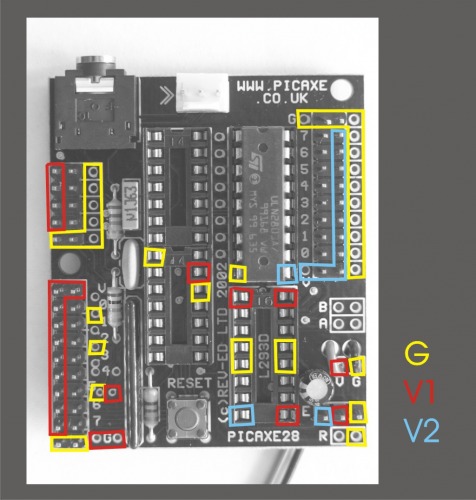
2 power supplies: See illustration below. Take off the jumper, and connect a seperate power-supply to V2 (and that power supplie’s G to ground, goes unsaid from now  - and the board will have V1 to the circuits and inputs, V2 to power external stuff, and G for all of it.
So if you hook up a board with 2 power-supplies, this is where you have current and ground: