Ok, to make sure I would not mess up I got a little help reading the circuit from Instructables. After following this word for word, I found that my circuit simply did not work, and when I touched the transistor it was extremely hot.
Here is what I put together following the instructions:
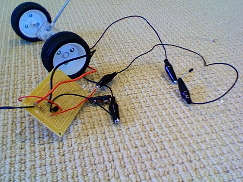
[Honestly, that's the best photo I got.]
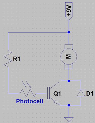
And here are the instructions I followed:
"Solder the motor and the resistor to the + 9v battery. Then solder the other end of the resistor to the photocell and connect the second pin of the photocell to the base (middle pin) of the transistor. Attach the other pin of the motor and the
- side of the diode to the collector (right pin loking at the flat side) of the transistor.Finally solder the + side of the diode and the emitter (left pin looking at the flat side) of the transistor to the - wire on the battery. "
Can someone let me know how to fix this?
Thanks :)
What are your component
What are your component value? Transistor type, resistor value, motor resistance, etc. Too much info is better than not enough.
Is the little black LED type thing on the right (in the clips) your photocell? It looks more like a photodiode, which means you have to worry about polarity, and your base resistor will probably have to be larger.
I’m using a NPN transistor,
I’m using a NPN transistor, a 1K resistor, and an IN194 diode. Fortunately photocells are the 1 thing I’m not short on, I’ll test some others out.
Update: I get the same
Update: I get the same result regardless of what photo resistor I use: the wheels continue to slowly turn even when I unhook the photocell.
Suggestions
Without knowing the specs on your transistor, it’s doubtful it will handle your motor current. The resistor should go from the base of the transistor to ground and the photo resistor should go from base to +. Normally you do not try to run motors off a 9 volt battery, (insufficient current).
The value of your resistor is way too low, even when hooked up properly. You need to use an ohm-meter and measure the light and dark resistance of your photo resistor. Pick the value that corresponds to the light level you want the motor to turn on with. The value of the fixed resistor, (when hooked up as detailed above), should be such that it will put about .7 volts on the base of your transistor to turn it on.
If your transistor was getting hot, it probably is no longer good.
PS
The 1N914 diode is a high speed LOW CURRENT diode and not intended as a “snubbing diode” as you’re trying to use it.
There are many many
There are many many different types of NPN transistors out there, you may have overloaded the one you’re using, or it may be connected incorrectly. If there’s no path from the +9V terminal to the base of the transistor it shouldn’t allow any current through the motor, unless it’s broken.
It’d also be nice to get some details on the ‘photocell’ you’re using, as it really does look like a photodiode instead.
I also strongly recommend
I also strongly recommend getting yourself a breadboard. Repeatedly soldering and unsoldering components during prototyping is a pain, as well as a good way to toast more sensitive parts.
I plan on getting a
I plan on getting a breadboard once I have enough money. The transistor is a NPN 2N3904 by the way.
And can you recommend a different diode I can use?
Thanks 
The 2N3904 is a low-current
The 2N3904 is a low-current small signal transistor, with only 200mA maximum collector current. With a low Vcesat of only 0.2V, your motor would have to have a stall resistance of at least 44Ω for the transistor to operate safely, but your motor probably has a stall resistance of only a few Ω so several times the maximum current will flow through the transistor.
Your motors look pretty small, are they OK running on 9V?
As for diodes I usually use IN4007s for protection, since they can tolerate 1A continuous and up to 1000V reverse surge, but they’re very cheap and easy to get where I live.
If you measure your motor’s resistance when it’s not running you’ll get the minimum (stall) resistance of the motor, which you can use to calculate the maximum current running through it for a certain voltage supply.
Breadboards cost $5-$10 for
Breadboards cost $5-$10 for a non fancy but still fully functional one. It will save you at least 10 times tjhat in parts over the years. I breadboard EVERYTHING before I use solder.
Alright, I’ll get the parts
Alright, I’ll get the parts you recommended and try again. I’ll let you all know how it goes.
Thanks


