

I salvaged some photo-interrupters from some printers and scanners. Thinking they would make good sensors, I decided to use them as encoders on my robot (which I haven't posted yet). However, I ran into several problems along the way. Since I learned a few things by overcoming these problems, I thought I would share.
Problem 1: How do you hook these things up?
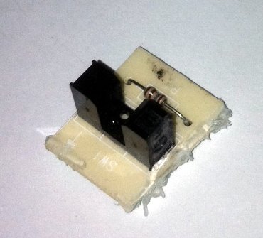
A photo-interrupter is a black u-shaped part. It is used a a limit switch or encoder in many printers and scanners. Inside the black case are two parts: an IR LED and a photo-transistor. The two parts are lined up so that the LED shines across the ends of the 'U' onto the photo-transistor, unless something is blocking it. This makes it very useful as the sensor for an encoder wheel. The photo-interrupter itself has 4 pins, two for the LED and two for the photo-transistor. Most of them are wired up in an 'open-collector' configuration. What this means is that the grounds of the two parts are wired together. That leaves three connections to make: power, ground and signal. In order to make the part work, two resistors are needed. First a current-limiting resistor is needed between power and the input of the LED. If you leave out the current-limiting resistor, you will fry the sensor. Values for the current limiting resistor can vary a lot from 180 ohms up to 2.1K ohms. The second resistor is a pull-up resistor on the signal line. This is needed to make the output of the photo-transistor a logical HI when the slot is blocked and the LED is not shining on the photo-transistor, connecting it to ground. Values for the pull-up resistor can run from 2K ohms up to 470K ohms.
Finding the exact values needed to make the photo-interrupter work is a bit tricky. I had to play with different values of both resistors to get a good response. The idea is to have a high enough voltage when the slot is blocked to register as a HI input, but also be close to ground when the slot is not blocked. If it doesn't get to ground, then either the current-limiting resistor is too strong or the pull-up resistor is too weak. If the signal line doesn't get high enough, you may need to lower the resistance on the pull-up resistor.
Problem 2: too many interrupts
After I got the resistor values sorted out, another problem popped up. I had hooked the signal output of the photo-interrupter to an interrupt pin on the microcontroller. However, each tick of the encoder wheel produced lots of interrupts instead of just one. After consulting various datasheets and an oscilloscope, the problem turned out to be that the output of the photo-transistor was spending too much time in the "no mans land" between LOW and HI logic levels. It kind of wandered up and down instead of jumping to the proper level.
The solution to this problem is a neat little device called a Schmitt trigger. What it does is to clean up the input by ignoring all the wandering around. The result is very neat and sharp transitions between LOW and HI. Exactly what the microcontoller likes to see when it's generating interrupts. The most common form of a Schmitt trigger is an inverter. The part number is 74LS14, and there are six in a chip. You still need the pull-up resistor on the signal line going into the Schmitt trigger.
Problem 3: crosstalk
With my encoders installed on the gear train of my robot, another problem showed up. When turning one encoder wheel, interrupts were being generated on the other encoder, even though the encoder wheel was not moving. After several rounds of tracing things down, it turns out the the noise was coming from one of the motors, even though they were on separate power sources. This was causing the LED of the photo-interrupter to fluctuate. It was tricky to find because the voltage was fine - it was the current that was changing.
To solve this problem I had to install some decoupling capacitors. A decoupling capacitor is a small value (usually 100 nano-farad) capacitor that sits across the power and ground lines. It's job is to redirect the noise through the capacitor and away from the rest of the circuit. After attaching the capacitor in parallel with the LED of the photo-transistor, the noise disappeared. I also put one between the power and ground pins of the 74LS14, which I read is a good idea for all logic chips.
Now I have a pair of encoders built from two salvaged photo-interrupters and home made encoder wheels that give nice clean noise free signals to my microcontroller. I had to add the 74LS14 and a couple of capacitors, but these are very low-cost parts and should be readily available. I hope that what I learned along the way is useful to others who are working on their robots.