TL;DR;: 8 A per h-bridge/channel/motor/inductive load at up to 22 V DC with only passive cooling (i.e.: open to the air) at room temperature (defined as 25 °C). So you can hook up two loads that need up to 8 A at 22 V DC (short peaks of up to 15 A are OK). The lost on these power MOSFETs is very negligible. At 8 A it is at most 0.064 V DC. If you are at a colder temperature or use active cooling you can probably push them to a higher voltage/current combination but stay careful!
See below for the full analysis on how to obtain this info from what was in the product description! 
The official manufacturer specs are up to 8 A continuous (at 22 V DC) and up to 15 A peak (brief).
The product description does mention the 2x H-Bridges are made of:
The info for this part is pretty easy to find here.
This part come in two packages, IRF3205SPbF and IRF3205LPbF:
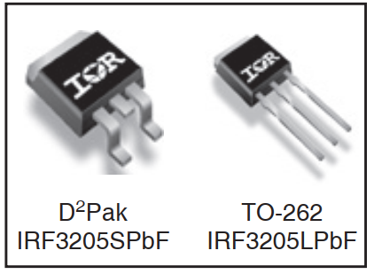
The board seems to be using the larger version of the module:
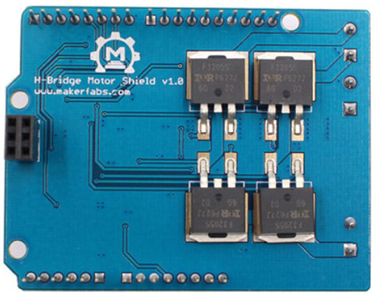
The schematic also confirms it is a simple H-Bridge design for each H-Bridge channel:
Furthermore, those 2 H-Bridges are driven by two half bridge drivers each (IR2104S) and seem to be following the manufacturer’s typical connection setup:
OK, so with all that info we can make some educated guesses at the real specs (for one channel/one H-Bridge).
First, we look at the maximum ratings:
The important value here is not the maximum current or voltage (those are pretty high) but the
Power Dissipation at 25 °C (typical “room temperature”). Without any active cooling, this MOSFET package can dissipate at most 200 W without heating up. As you can see, its specs drop as the temperature goes up (from max 110 A to 80 A). The next line,
Linear Derating Factor tells us that if heats up by 1°C for each excess 1.3 W not dissipated from the chip.
Now, from the official specs we had 22 V DC and 8 A continuous. Since power (W) for an electrical signal can be determined by voltage (V) x current (A) and typically the voltage is fixed (22 V), we can do a rough calculation using a voltage of 22 V DC: 200 W / 22 V DC = ~9.09 A. Of course, this 9 A value is the absolute maximum ratings for the chip (when used at 22 V DC and ignoring any loses and inefficiencies), so you’d want to use a lower value (maybe 10-20% lower).
Oh, look at that! The official specs as we said above are 22 V DC / 8 A continuous, or ~12% lower than the absolute ratings! So, with this info we can say with good confidence that in most cases you can use a 22 V DC source and power motors that require up to 8 A continuously with only passive cooling (i.e.: open to the air) in a room at 25°C.
As for your voltage drop question, we simply have to follow to the next page (# 2) of the MOSFET datasheet to see the rest of the info in the two tables:
Those two tables give us two important pieces of info… ok, all the pieces are important but for voltage drop there are 2 main ones:
-
In the first table we have the Rds(on). This is described as the Drain-to-Source On-Resistance. MOSFETs (a type transistor) basically acts like a resistor when it is turned on (and a “open circuit” when off; lets ignore leak current here).
This value tells us that the worse case scenario for these MOSFETs is a resistance (when on) of 8.0 mΩ. Since we can calculate the voltage that will be wasted by this “virtual resistor” in series with your load (the motor) easily (V = IR), lets do so for the worse case, 8 A of continuous current. 8 A x 8 mΩ => 8 V DC x 0.008 Ω = 0.064 V DC.
So, in the worse case scenario, your circuit - if providing 8 A to a DC motor (or other load) - will lose at most 0.064 V DC. And now you know why we use power MOSFETs in these designs: they are cheap, cost effective and really good at this task!
-
The second table tells us of the Vsd, or the Diode Forward Voltage. This is the amount of voltage that is lost on the reverse path (typically from an inductive load when switching the H-Bridge off or reversing direction). Since the board uses half-bridge driver chips it is safe to assume that they take care of switching the MOSFETs properly within specs. This is even more true in this case considering both parts and the design come straight from the manufacturer of those components.
Enjoy the info and good luck with your project!
Sincerely,


