

After following instructions to a tee, double checking all operations, and downloading program, we are still having a problem with our "STARTER ROBOT". The 2A and 2B wires are connected to seperate motors. One motor does not operate. The motor that is connected to 2B wires does not operate. We tried switching wires, before they were soldered, and the opposite motor worked. All connections have been double, and triple checked to make sure they are secure. There seems to be no way to check for continuity, because we are attached to the board? Can you help us out? Another school project we need to correct ASAP.
Can you un-attach motor from
Can you un-attach motor from the board and test it with a battery? If you have a dead motor, you will need to replace it.
Both motors were working
Both motors were working before soldering, per previous statement. Wires were swapped and the one motor connected to "B-side" of board did not operate.
**Meter? **
If you have a multimeter, you could check to see if the L293D chip is outputting anything to the motor. If nothing is being put out, then check the inputs, to see if the PIC si driving them. Also check ot see if the chip is well seated. Also check the Enables on the L293D to see if they are near 5 volts. If no signal on inputs, it might be good to check over the code one more time, as it is very easy to gloss over something.
One note also, soldering can damage the motors connections if there was a mistake. It might be good to touch some battery leads to each one just to ensure they are still passing a current.
One mistake I made, when I
One mistake I made, when I assembled my first bot was, that one of the wires on the motor touched the metal on the motor casing (or do you call it housing???). I had stripped off too much insulation if the wires, but it can also happen with too much solder or a bad soldering.
The pins 4,5,6&7 should also
The pins 4,5,6&7 should also be affected / be high when you write “high 5” etc in the code. So there are 2 places to check / measure:
These pins, and the motor-controllers output, the a/b. A multimeter would work wonders.
Also, I’d like to see your code?
I can get both motors to
I can get both motors to operate by jumping connections on the board. I am not sure exactly how to know the number of each pin. There are no #'s on my board where the L293D is located. I have a multimeter, and i am getting just under 5 volts from battery connections and every other place on the board that gets a voltage measurement. Chip is well seated, but I don’t know how to check the “Enables”. Code has been double checked for accuracy, it was cut and pasted to the Editor from https://www.robotshop.com/letsmakerobots/start?page=1.
Pins and voltages
Frits has a good tip/walkthrough here for the PICAxe AXE020 board. This image :
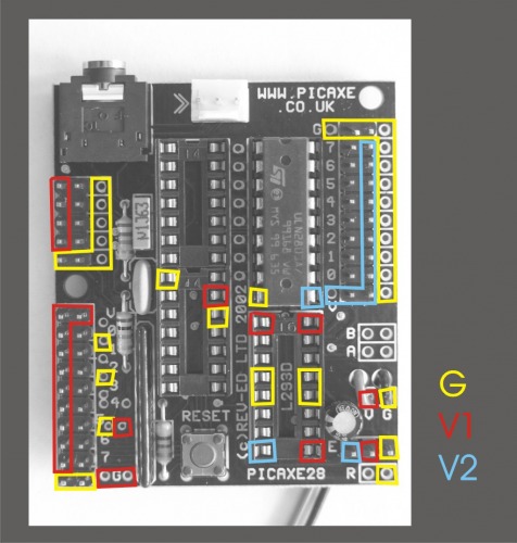
shows red where the L293D should show 5 volts or so. The Enables are the red upper left corner and the red lower right corner, pins 1 and 9 of the L293D chip. I was guessing that the lower right pin might not be 5 volts, which would prevent any output from going out from that half the chip, stopping motor drive.
About pins 4,5,6,7, check this picture :

If you look at the tan pins corresponding with F, there are small numbers beside them that are even with the magenta holes corresponding with E. The E holes are directly from the processor, and the upper 4 are the 4,5,6,and 7 points that should be sending signals to the L293D chip. The holes 4,5,6 and 7 probably connect directly to the L293D pins 2,7,10, and 15, numbered clockwise around the chip starting from the upper left. Each of those pins should be swictched according to the code, to allow the L293D driver to send power to the motor.
Note if hole 4 is high,5 volts, and 5 is low, 0 volts, then one motor should be turning in one direction. Switch to hole 4 low and hole 5 high, the motor should then turn the other direction. Same with holes 6 and 7, if the enables have bene brought high.
CONTINUITY
I am getting voltage readings on all holes, 4,5,6, and7. I checked voltages when wheels should both be moving forward. They all seemed to be appropriate, but we still only get one wheel to operate. Continuity is good to all connections and board, also to holes 4,5,6, and7. Can there be false continuity readings?
When code is “symbol danger level” both wheels shoud move? This is where I was getting voltage readings that actually register. I am using an analog multimeter.
The bottom line is if I am getting voltage reading levels, and continuity that are appropriate, I don’t understand why the one wheel is a problem. Is there a certain spot on the board that voltage is checked from, and I am doing it from the wrong pins? Or can there be anything else that a novice can be doing wrrong that I am not aware of?
Volts, not connection
The measurement being made is for the presence of a voltage at a particular point, not whether there is a connection between points. There should not be false 5 volt readings. Since the points 4,5,6,&7 are reading as working, the possibilities go to the L293D chip being fried, or missing a connection, or the motor being fried or missing a connection. I think you said the motor tested ok when being switched, so the remaining thing to test is the L293D chip. As noted, the voltages at pins 4,5,6,&7 should also appear on the L293D chip at its pins 2,7,10,&15, numbered clockwise around the chip starting with the upper left with the chip notch away from you. There may be that 28X board pin 4 corresponds to L293D pin15 or some such, but just as long as one voltage drives one chip pin, things are ok. As noted before, L293D pins 1 and 9, the enables, should be at 5 volts at all times. Once all these inputs check out, then the outputs must be measured when a specified input is at 5 volts. So of L293D pin2 is high, then the output pin 3 should also be high, perhaps a volt or so below the voltage you have for the motors. If using the same batteries for both the motors and the board, then the output should be 3.5 to 4 volts. In checking the rest, a pin 7 at 5 volts should have a pin 6 at 3.5-4v, pin 10 at 5 volts should have pin 11 at near 4 volts, and lastly pin 15 at 5 volts should have pin 14 near 4 volts. Go over these, to see if the chip is not changing, and if it is, then there probably is a problem with the motor connection somehow, possible short or open circuit.
I think I found my problem
I think I found my problem as being a bad solder joint (my fault). Everything seems to work per code, except the motors going at different speeds. The robot does not travel straight. With all these different voltage readings, does this affect the speed? Is there a good program so that the robot will find it’s way through a maze? This is what our science project is to accomplish.
Motors and wanderings
Motors and voltages will always be a little bit different than each other, so different approaches can be made to help out. One is to add encoders to the motors, to keep track of how fast one is moving, and then adjust the voltage with PWM to speed or to slow it. Another is to simply not worry about whether the robot is going straight and simply keep track or where it is traveling, steering away from obstacles. Maze solving can be simple right-hand rule (aways turn right at an intersection) to involved A-star mapping. Simplest would be top make a maze that can be solved by the right-hand rule (or left) to stop on a spot when done (simple light/dark detector facing down). You could even make the robot appear smart by looking down the left passage, before turning right.
Robot that doesn’t go straight
After reading about building our 1st robot, initially, and the cost being $85, I have spent well over $100 on this project to try and make this project work. The idea was a science fair project to test the sensitivity of an “IR” ROBOT. From the description everything seemed simple. Solder a few wires enter some code, and away we go. After about three weeks and numerous messages and trips to the store and purchasing the USB cable,I am being further instructed to add encoders. Will that be the end, or will there be more? How much are encoders, and are they easy to install? To get our robot through a maze of different material to test the sensitivity, I can’t picture having a “right turn only” maze that would be appropriate. Is there any other ideas that might be worthy that don’t need much more in the way of time or money? Project is do soon.
Getting the story straight
Would you care to explain a little more about your maze? Is it a specific structure, or can it be built any way that is needed? What are these “different materials” that the robot is supposed to detect? How are you intending to measure “sensitivity”? More details about your project would get better answers, as would less complaining about cost and time.
Here is a picture of a maze that would be solved by the right hand rule. The red robot should be programmed to follow the wall on the right, indicated by the green line. In this case the robot could even continue to follow the outside of the maze back to the start to drive through it again. In this situation, the robot doesn’t need to go straight, only to follow a wall. Perhaps the different materials could be placed on that right wall, to somehow be measured as the robot passes.

The project is to test the
The project is to test the sensitvity of the robot on differing materials. Glass, a mirror, differing thicknesses of paper, and/or cardboard, and wood. And how far away it detects the given material before it has a reaction to it. The maze itself is not constructed, and can be made any way to perform and test it’s functions. The way I had always pictured constructing the maze was to have the obstruction, or different material being set as to where the robot would sense it in front of it before making a turn. All of the measurements would be distance of reaction to.
Also how do we get the robot to proceed further down the right hand walls before it stops to look for obstuctions left or right. I couldn’t get from the manual, or the code which parameter I need to change for that to happen.
I’d recommend dividing the
I’d recommend dividing the project in two parts:
First a testbed to discern the sensitivities - a yardstick with the sensor mounted at 0, and a movable mount for the material in question.
and second the actual robot in the maze - probably made with the cheapest material tested, provided the sensitivity test shows it is appropriate.
For your final question, the answer lies within - Make program logic to do what you want.
Measurable change, and code comments
There may be some difficulty in measuring any significant difference in distance of detection, as the sensors do not change their readings much with different materials. Some tests of just the sensor connected to a power source and a meter might verify some of these charecteristics, and if there is a way to demonstrate some sort of change in range based on robot reaction. Perhaps this measurement should be a seperate part as suggested, and the maze solving be a seperate part.
Frits has comments in his code that show what each section is doing. Comments that are not part of the program are shown with a single quote mark and space in front of them, so the interpreter does not attempt to run them. The “main” routine here :
main: ’ the main loop
readadc 1, b1 ’ read how much distance ahead
if b1 < dangerlevel then
gosub nodanger ’ if nothing ahead, drive forward
else
gosub whichway ’ if obstacle ahead then decide which way is better
end if
goto main ’ this ends the loop, the rest are only sub-routines
begins with a reading of the sensor and storing that measurement into a variable. The next line tests “if” the reading is less than a preset dangerlevel. If so, it drops down to a routine called “nodanger”.
nodanger:’ this should be your combination to make the robot drive forward, these you most likely need to adjust to fit the way you have wired your robots motors
high 5 : high 6 : low 4 : low 7
return
whicch simply switches the outputs to the motor to drive the robot forward.
The variable dangerlevel had been defined at the very start of the code here:
Symbol dangerlevel = 70 ’ how far away should thing be, before we react?
and is the parameter that can be changed to get the robot to turn earlier or later. This might need to be made larger to get the robot to drive in a maze hallway in close quarters.
The “whichway” section :
whichway:
gosub totalhalt ’ first stop!
‘Look one way:
gosub lturn ’ look to one side
pause servo_turn ’ wait for the servo to be finished turning
gosub totalhalt
readadc 1, b1
’Look the other way:
gosub rturn ’ look to another side
pause servo_turn ’ wait for the servo to be finished turning
gosub totalhalt
readadc 1, b2
’ Decide which is the better way:
if b1<b2 then
gosub body_lturn
else
gosub body_rturn
end if
return
should probably be changed to get the robot to always turn right if there is an opening there. Perhaps to :
’ Check to if right turn is possible
if b2<dangerlevel then
gosub body_lturn
else
if b1<b2 then ’ do check for direction to turn
gosub body_lturn
else
gosub body_rturn
end if
end if
return
I have no way to test this code, as I do not have a PICAxe, nor have I ever programmed one.
It appears from the code that the robot is always only looking forward, never checking the right or left to see if it is getting to close to a wall. As your robot (or any robot for that matter) does not drive straight, there probably needs to be some side checking to prevent running into the wall. It would be helpful to know which direction your robot tends to curve, to develop code to correct for this, Assuming it curves to the right, the following may allow a periodic check and correction of the robots heading :
’ Check right
checkright:
gosub rturn ’ look to right
pause servo_turn
readadc1, b3 'get a quick reading
if b3<dangerlevel then
gosub body_lcurve
end if
return
body_lcurve:
high 6 : low 5 : low 7 : high 4 ’ this should be your combination that turns the robot one way
pause halfturn
return
Note that this introduces a new varaible that should be added to the top of your code, the halfturn.
symbol halfturn = 150 ’ this sets how much should be turned
Also the pauses and halt has been removed where it is included in other subroutines. I felt these corrections should be made as the robot is moving, not stopping as they were made. Adjustments should probably be made as the robot is observed, to make the best response to the maze environment as possible.
Try a few things out and see who the robot reacts.