Need help - Interfacing an Electret mic to a microcontroller

Since I have some extra days this weekend I decided to blow the dust off my brat and begin woking with it again. As many may know, with the help of others, I built a custom board that enabled my bot to react to sound. Im looking for a simple alternative to do the same thing. I’m using a Basic Stamp 2px which has the following modes:

BS2px Mode Values: (CONFIGPIN command)

0 (or SCHMITT): Schmitt Trigger
1 (or THRESHOLD): Logic Threshold
2 (or PULLUP): Pull-up Resistor
3 (or DIRECTION): Output Direction

BS2px Mode Values (COMPARE command)

0: Disables comparator.
1: Enables comparator with P0 as Result output.
2: Enables comparator without P0 as Result output.
Result Values 0: Voltage P1 > P2; P0 optionally outputs 0.
1: Voltage P1 < P2; P0 optionally outputs 1.

I want to use the COMPARE command to compare voltage levels from each mic.

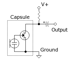
Right now, I only want to know how to interface the mics that are mounted in my bot head. Below is a rough guess as to how it could work. Any help is greatly appreciated.

http://img7.imageshack.us/img7/4044/micb.gif

um that circuit will eat your mic for lunch.

you need the resistor between the +5V and the mic pin.
then connect the stamp pin to the junction between resistor and mic pin.
depends on the mic bias voltage level what voltage you are going to see on the stamp pin.
you will find that varying the value of R1 will change the p-p output level from the mic.
to optimize this setup a tone of around 3khz and fix the mic and speaker a few inches away from each other.
now use a DMM in AC-volts mode to measure the voltage on the stamp pin.
Adjust R1 to maximize the voltage seen on the DMM and note it’s value.
Now set the frequency to about 1KHz and repeat the process.
Don’t be surprised the value of R1 may different at the lower frequency
Just average the two R1 values together and use that result as your R1.

Thanks Eddie, Ill give that a shot. I was not sure about putting a resistor between the 5v and the mic since I thought the mic needed 5v to operate.

Here are the specs:

radioshack.com/product/index … =techSpecs

eh that’s an odd looking duck. usually electret mics have only 2 leads but that looks like it has 3. was there a connection picture on the back of the package when you bought it?

No there sure wasn’t. I tried looking at it again but it was hard to see in side the skull. I sorta remember the ground and signal wires were tied together. The exposed braided wire was soldered to the outer case, however, I noticed a small aluminum trace linking the outer case to one of the pins. So really it only has two pins: a red wire, black & white for GND. Not sure why they did it this way.

So here is how I pictured wiring it up to the ABBII. I have a shunt to use the regulated 5v output. The yellow wire will have the proper value resistor using the tests you described earlier. The only thing not clear to me is if a ressitor should be used for the pos. lead.

http://img14.imageshack.us/img14/7295/abbssc32wiremod.gif

mike using your last picture you would configure the yellow wire P3 as your 5V output and use the red wire AX3 as your signal input.

an electret mic works because it is a FET with it’s gate coupled to a pzt or other piezzo sensing device. the FET allows some small amount of bias current to flow and therefore develops a voltage drop across the series resistor. when sound waves hit the pzt and make small amounts of charge it drives the gate of the FET and gets amplified as a voltage across the resistor.

look at it this way… if you drove the red wire to 5 volts and measured the voltage on the yellow wire then how would you ever see anything but 5 volts output?

I’m a little confused… Red is 5V input and yellow is voltage out to P3 like you mentioned in the first paragraph. Since two wires share the same Net, the only difference is the resistor location. So are you suggesting to switch the resistor to the red wire, and nothing on the yellow wire?

Taking a second look, I see that current takes the path of least resistance so the red wire will be constantly at 5v and I assume this is what you meant by the yellow wire always seeing 5v for ever. If I put the resistor on the red wire and not the yellow, then current has no choice but to go through the red wire and the sound going through the mic will induce/create differences in signal potential for P3 to read. Am I right? huh Eddie? huh? :laughing:

I think you will need an opamp to make the microphone output measurable. The last one I used I needed to amplify X 60 to get a usable input signal. Easy to do with a 741 opamp.

The BS2px’s built in compare pins are sensitive enough to react to your finger touching the pins. I don’t think I need to use an op amp in this situation. as long as there is a variable input voltage, I should be able to compare the differences between the two mics.

Mike there isn’t much more I can say to explain how to hook up your mic. RE-read what I said, it deosn’t say what you repeated after my post, and if you have to then look up on the net how to hook up an electret mic and why it works the way I’ve described. If you put +5V on the red lead going directly to the pin of the mic not only will you not get any output other than 5V on the yellow wire but it could damage the FET inside the mic.

In my post I explained how to connect the mic, why it needs to be connected that way, and how to optimize your selection of a bias resistor value. Power supply on the yellow wire with the resistor between power and the mic pin, signal out on the red wire. It doesn’t work any other way and I’m not sure how else to tell you that. Please don’t get stuck on wire colors or trying to find another way, just hook it up like I said and it will work. :open_mouth:

And for the record russ is probably right and you’ll need an amplifier but I was just taking baby steps and trying to get you crawling with the mic properly powered first before jumping to the next step. what you will discover while selecting the bias resistor is you will only get a few tens of milivolts out. this is plenty to calibrate the resistor but there is a whole nother issue you have not discovered yet relating to the bias point the FET in the mic decides to operate at and how that changes based on temperature that is going to mess with your comparator approach. we can cross that bridge when we come to it… probably with an op-amp. :wink:

Well, just reading the discription on the RS page and looking at the pix (looks like two wires, red and black). I’d guess that the red wire would be connected to the +5v power supply and the the black wire to the audio in pin. I’d say that there is no need for a resistor in the circuit as the spec already gives a voltage range spec (aka it already has an internal resistor that handles the speced voltage ranges). Perhaps you can do some tinkering with the mic on the mic input on your computer to see if you can get it to work there. Mikes one buys for computers and such are two wire setups. I’d assume this mic is similar in that any specific needed circuits are already handled internal to it.

This omnidirectional microphone element has a wide 30-15,000Hz frequency response. Requires 4-10VDC.

http://RSK.imageg.net/graphics/product_images/pRS1C-2160123t98.jpg

Another schematic.

en.wikipedia.org/wiki/Electret_microphone

I read over and over what you said, and belive me, I’m trying to the best of my ability to follow what you are saying. I don’t know what I am doing which is why I posted for help on these forums. If I knew what I was doing, I would not have asked for help. :laughing:

I have read, re-read, and read again all of your post and I really don’t know what you are suggesting without any visual aids. It sounds to me that infact you are suggesting to swap the red and yellow wires as I have posted earlier. I have created a new diagram using your descriptions on how to hook it up. If I am still on another universe away in terms of getting it, then perhaps I need to move on to something else such as IR vision and scrap the mic idea. I really want to understand what you are trying to say, but I can’t help it if i’m not able to picture “what goes where”.

http://img18.imageshack.us/img18/9157/abbssc32wiremod2.gif

I tried out the COMPARE command last night using the regulated 5v output as the input source. When I get around to it, I need to wire up the mics in my skull to try it out. I regret cutting the leads so short, but I was wanting to replace the wires with a higher gauge wire because 22 is to thick and stiff.

Thanks Eddie for your help. I understand it now, and this old geezer can actually learn new tricks with lots repetition. :laughing:

Here is the example code that I will be modifying for the two micophones.

[code]’ COMPARE.BPX
’ This example demonstrates the use of the COMPARE command.
’ Connect two variable voltage sources (0 to 5 volts) on I/O pins
’ P1 and P2 (or a button on each pin connected to ground). Run the
’ program and watch the Debug Terminal display as you adjust the
’ variable voltage or press the buttons.

’ {$STAMP BS2px}
’ {$PBASIC 2.5}

#IF $STAMP <> BS2PX #THEN
#ERROR “This program requires a BS2px.”
#ENDIF

result VAR Bit

Setup:
’ P0 = output, all others = input
CONFIGPIN DIRECTION, %0000000000000001
’ Enable pull-ups on P1 and P2
CONFIGPIN PULLUP, %0000000000000110

DEBUG CLS,
“BS2px Comparator Demonstration”, CR,
“==============================”, CR,
CR,
“Input Voltage: P1 > P2”, CR,
“Output State: P0 = 0”

Main:
DO ’ Display P1/P2 comparison
COMPARE 1, result
IF (result = 0) THEN
DEBUG CRSRXY, 18, 3, “>”
ELSE
DEBUG CRSRXY, 18, 3, “<”
ENDIF
DEBUG CRSRXY, 19, 4, BIN1 result
LOOP

[/code]

If you are just comparing a voltage, then I would think you would need a capacitor/resistor setup such that the mic output would charge the capacitor to a ~stable voltage for reading. The louder the sound, the higher the stored voltage in the capacitor.

I was thinking about that because the differences are going to be constant. Ill need some sort a filter for sure.

This weekend I want to experiment using the BAPs ADC pins AX0-3. I found a simple Mic preamp that I will be using to connect to the AX0 pin. Is the below code what I need to display the value? This is just a rough draft. :laughing:

[code]micValue VAR Word

Main:

ADin 0, micValue
pause 1000
DEBUG [DEC micValue]

Goto Main[/code]

Here is the schematic of the pre-amp: Note C2s output will connect to the AX0 pin on the BAP.

First thing that jumps out at me is you should use a 5vdc supply to ensure the output of the mic will not go above 5vdc. That would kill the A to D input.

I was going to jumper one of the normal pins to use the regulated 5v supply on the BB2 to power the preamp, and then use the AX0 pin to read the output. If all goes well, I will have a pin go high when the signal level reaches a certain value, which will turn on a LED. If that works, then I can develop a program that can have the bot listen for noise at set intervals and react based on the signal level.

Would it be safer to add say a 420 ohm ressitor in series with C2?

Not needed.

Ok I have some problems here. First I bread boraded the above schematic for the mic and I could not seem to get a readable signal beyond 0.00v So for the time beaing I downgraded to an even simpler circuit using a photo cell. I cant seem to get my mic do do anything so I suspect it might be bad. Untill I can buy a new mic, ill have to make do.

Here’s the schematic I am using to help me write a program that will read the input using the AD feature of the BAP.

http://img25.imageshack.us/img25/581/bb2photosch.gif

Here’s how I have it hooked up: Note the two wires on top are regulated 5v supply connected to the bread board. Sorry about the blurry pic. It’s a pic from my cell phone.

http://img26.imageshack.us/img26/6384/bb2wired.jpg

no matter what the output is 0v to 4.5 v I get a value 1023 in the terminal window. I’m using IDE 8018. Here’s the code I am using:

[code]micValue VAR Word

Main:

ADin 0, micValue

'Debug [DEC micValue,13]

serout S_OUT, i57600, [dec micValue, 13]

micValue = 0

Goto Main[/code]

micValue is the voltage level output by the photo cell.