Need consistent 90 degree turns. HMC5883L and Arduino Mega

I am currently working on a project for school. The idea was to create a robot that could perform pathfinding functions using A*. The path is found using a virtual grid of nodes programmed into the Arduino where "X"s are non-passable objects, "0" as the start, and "1" as the destination.

Not sure how to insert code on this forum. Someone could help me out with that as well...)

Example: 

  char createPlane[][planeSizeX] = {{'.', '.', '.', '.', '.', '.', 'X', '.', '.', '.', '.', '.', '.'},
                                    {'.', '.', '.', '.', '.', '.', 'X', '.', '.', '.', '.', '.', '.'},
                                    {'.', '.', '.', '.', '.', '.', 'X', '.', 'X', '.', 'X', 'X', 'X'},
                                    {'.', '.', '.', '.', '.', '.', 'X', '.', 'X', '.', '.', '0', '.'},
                                    {'.', '.', '.', '.', '.', '.', '.', '1', 'X', 'X', 'X', 'X', 'X'},
                                    {'.', '.', '.', '.', '.', '.', '.', '.', '.', '.', '.', '.', '.'},
                                    {'.', '.', '.', '.', '.', '.', '.', '.', '.', '.', '.', '.', '.'},
                                    {'.', '.', '.', '.', '.', '.', '.', '.', '.', '.', '.', '.', '.'}};

The instructions for the path above would be: left, left, up, up, left, left, down, down, down
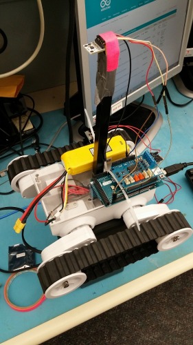
 

Current parts:

Dagu Rover 5 tracked robot (no encoders, 2 motors)

Arduino Mega 2560

Arduino Motor Shield

HMC5883L magnetometer compass

My pathfinding application works great and I know I am building the correct instructions for the robot to follow. At this point, I have already spent weeks just trying to get this thing to turn 90 degrees consistently. It is vital for my robot to turn as accurately as possible in order to arrive at the correct destination.

I bought the HMC5883L compass hoping that it would allow me to turn 90 degrees. I have gotten to the point where it will turn until the correct heading is reached (according to the compass), but it is not consistent at all. Sometimes too much, sometimes not enough.

Currently, I am taking an average of the X and Y readings along with the adjustment values for X and Y that I calculated using this http://forum.arduino.cc/index.php?topic=149073.0. I believe I have correct declination for my area as well.

float getAvg(float array[])
{
  float average = 0;
  for (int i = 0; i < 5; i++)
    average += array[i];
  average /= 5;
  return average;
}

float getHeading(HMC5883L &compass)
{
   float declinationAngle = 12.183;
   float xScaled[5];
   float yScaled[5];
   //MagnetometerRaw raw;
   MagnetometerScaled scaled;
   for (int i = 0; i < 5; i++)
   {
     //raw = compass.ReadRawAxis();
     scaled = compass.ReadScaledAxis();
     xScaled[i] = (scaled.XAxis - xAdj);
     yScaled[i] = (scaled.YAxis - yAdj);
   }
   float xFinal = getAvg(xScaled);
   float yFinal = getAvg(yScaled);
   float heading = atan2(yFinal, xFinal);
   heading += declinationAngle / 1000;
     if(heading < 0)
       heading += 2*PI;
     if(heading > 2*PI)
       heading -= 2*PI;
     heading *= 180/M_PI;
   return heading;
}

Even with all of this, I am still not getting the precision I need for turning. Please let me know of any ideas any of you have that would allow me to have the precision in turning that I am looking for.

Just a couple of
Just a couple of points:

  1. Tracked robots are sometime difficult to make exact turns with.

  2. By not using encoders you have thrown away the best chance you have of making precision calculations when combined with other sensors. Is there a reason you aren’t using encoders?

  3. An accellerometer can also be used to help determine how much a turn is. Perhaps by using data from multiple sensors you may be able to get a more accurate result.

  4. My last point is that there is a way to way to post more readable code here.

Ideas

You don’t say, but I assume that this will be in a maze.  Why not put limit switches on each side (connect a boom that hangs over the tracks with a limit switch on the end) so that if it does hit the side, it will adjust a bit toward the other direction?  Or maybe limit switches attached to the body of the Rover on the front and then stiff wire connected to the switches so they hang beyond the tracks.on the front of it?

If you have control over the maze, why not put electrical tape down the center of each of the corridors of the maze and add some line following sensors? 

Perhaps a combination of all the different sensors together can give you enough so that your bot will work well.  Good luck!

Regards,


Bill

Accellero / gyro
Ideally a gyro; may do the trick, as they are accurate enough over a short period. Its also rather easy to just add a gyro compared to other solutions. They won’t help too much with driving straight though (as that is a longer time period and gyro will drift), but I dont know whether that is a problem or not.

Thanks for the reply!

This is my first time trying to control a robot using Arduino. I’m a bit embarassed to say it, but at the time I bought the Dagu Rover 5 tracked chassis, I didn’t even know what an encoder was. Of course, now I do! I am just trying to make do with the money I have already spent. I was told by some others that sensors would do just fine and would be cheaper than buying another robot.

I went ahead and bought a MPU6050 board just yesterday to hopefully help me out. Are you familiar with this particular board?

Thanks for the link to post readable code! I am used to the Arduino forums where I can just use .

Honestly, I don’t have much useful to add.

The issue with tracks is slippage. You really need encoders and wheels. I would imagine your rover 5 already has encoders. You just have to read them and swap the tracks for wheels.

To go precisely cartesian

Try mechanum wheels and 2 motors, one moving on the x axis and the other on the y. Steppers are more precise.

A* may be best suited for a plotter which need to draw something without going over drawn walls. A* doesn’t work on a differential steering robot, because of inaccurate steering, known map may change and cells add unnecessary fragmentation in the space available.

School project?
Is this a school project where you have constraints that you haven’t told us yet, or are you doing this on your own to learn?

If it’s a school project you may be stuck with this, but if you’re learning on your own you may be able to use other sensors to aid the compass. This is typically called sensory fusion, and it may be possible to get more accurate information from a few different sensors than from any one of them alone.

For example, many balancing robots use a gyroscope, an accelerometer, and encoders to get the information they need for both balancing and movement from less expensive sensors.

You may be able to add encoders to your motors. There are some distributors that sell the Dagu magnetic encoders. You can ask OddBot about that.

Are 90 Degree turns really useful?

I personally would stick with a compass.  Encoders have their issues too.  If you have a flat floor, indoors, and it is truly a maze…then maybe encoders will help…maybe.  I’d still keep the compass, add some obstacle detection, reevaluate ALL of my assumptions about the nature of the problem (starting with ones about right angles), and think a lot more about software…a lot.

It can be difficult to turn in place precisely 90 degrees.  For my treaded bot, I made it so it got pretty close while rotating in place (say 8 degrees), but then as it started moving forward at all, it continuously adjusted the throttles to refine the heading to the 1-2 degree accuracy of the compass.  Before the bot had moved 2 inches it would be within a degree or two.  You can keep a robot driving in a (more or less) straight line along a desired heading, over smooth or rough terrain, with or without slips in traction on one side or the other, up or downhill.  You can alter the left or right throttle to make steering adjustments in direct proportion to the number of degrees error between the current heading and the desired heading.  This means that the bot will turn quickly when the error is large, but make very small adjustments when the steering error is small.

I would seriously question the need for precise 90 degree turns for a number of reasons.  First, can you even place your robot in an original starting position with a .25 degree heading accuracy?  Even if you could, errors would creep in as the robot moved AT ALL.  Treads have play, and wheels have their issues too.

What you need in my opinion is something that is self correcting (as errors will constantly creep in from multiple sources).  A compass is a big part of this.  Better software is also a huge part.  

Some thoughts on software, especially in outdoor environments…even though you are doing pathfinding in a space defined by a grid, doesn’t mean you have to navigate along pixels in the grid at right angles.  You can start with the pathfinding results, and then use some math to find more efficient diagonals through the “open space” in  the grid space.  There are formulas for determining whether a line intersects a polygon (obstacle) in a space.  If you imagine the problem from the perspective of the robot, the only thing that matters is which direction to drive.  Imagine seeing the obstacles from ground level…from the robots perspective.  Some headings are blocked, others are not.  You can determine the leftmost angle of a given obstacle or obstacles (typically the closest one) and the rightmost angle of an obstacle from the perspective of a robot and then test lines that steer slightly clear of that cone, making sure that this is still consistent with the overall A* result.  The result will likely be a lot more efficient than pathfinding alone. 

There are many things that could be done, these are just some ideas that I found useful.  A* or other pathfinding algos alone will often drive you directly into a large obstacle and then plot a hazardous course skirting it with many turns, when a human being would immediately see the opening to the left or right and go directly for the opening “around” the large obstacle, turning only once and staying well clear of the large obstacle.  That is why it helps to use pathfinding as a guideline, but also think of the problem from the robot’s perspective…“The opening is in that direction and its not a dead end…go for it”  We’re used to looking at grids top-down, but if you are a cell inside the grid, the grid looks like a line, where each pixel is an angle you could head in.

I would think you need some kind of obstacle detection system (like an infrared distance sensor on a servo) so that as obstacles get too close this can override or be correlated with the “map”.  The robot will lose track of its precise location in its map space and need to adjust. There are lots of algorithms for this as well, I wish I could say more on that.  As I said, errors will creep in.  What good is a precise degree turn if you don’t know exactly where you are and what your exact heading is to begin with?  In many cases, your heading will be off of where it should be and you’ll need to make a perfect 87 degree turn.  I question whether perfection is possible with anything in robotics…so continous self correction is good.

That’s all for now.  Hey, if you are doing a maze thing, you can use the same old stuff people have tried for ages…just know that each of these different sensors and algos have issues if used alone.  The world is not right angles either, the walls in a rectangular room are often out of square by several degrees as the framing and drywall people make errors.  Try not to trade one set of issues for another bigger set.

That’s my 10 cents.

Ayup, Martin, sensory
Ayup, Martin, sensory fusion.

I don’t know if kheyen’s robot is working in the real world or working from an imaginary map.

He’s getting a 6050 which is a step in the right direction. That gives him a compass, accelerometer, and a rate gyroscope. There seems to be Arduino support for the sensor, but I’m not sure how well written. It returns good results, but it might not pass the bdk6 test. :slight_smile:

I still think encoders have their place. And yes, in the real world a bot needs obstacle sensors if only to avoid the dog or small child who thinks “toy!”

Of course right now I really hate the real world, so the robots are welcome to it.

I’ve been looking at the
I’ve been looking at the 6050 on Google and it has a processor on board which is supposedly accurate and fast. This makes the 6050 a very cost effective part. Maybe this could be combined with the compass to get a bit more accuracy.

The problems of magnetometers can be that they are too sensitive. If you bring them next to the fridge they’ll probably be highly effected. Actually anything with a high amount of steel or motors, but the fridge often has motors at ground level. In fact, the kitchen is an unfriendly place for a small robot because they can get stepped on too easily causing a spouse, in this example, to become extremely angry. :slight_smile:

that’s a dollar at least!

Free range algoryhtms also are more interesting; A* it’s well known, but good AI for pathfinding on real conditions it’s trickier.
A good and simple algorithm it’s to head toward goal and scan for the largest distance near the exit, with a greedy heuristic, like distance/differenceDegree, go forward and recalculate.
This is prone to be trapped in local minima, like concave walls, to avoid that either go back or set goal to a random point and resume the original goal after a while.
3 HC-SR04 or a sweeping one should be enough.
If all obstacles are square you can check perpendicularity with two rangefinders at the same side, parallel to the wall. When turning and both sensors give the same value it’s perpendicular!
However range finders often have a resolution of 0.5-1.5cm, so you can’t have sharp 90°.

HMC5883L compass inclination

Just a small comment about the sensor itself. I have two HMC5883L compass sensors, one which I’ve been testing and another which I haven’t touched yet. I noticed when using my first sensor - It didn’t give very good angle values, turning it to face different directions, unless I actually tilted the sensor. Suggest to connect up, try different tilt orientations until you get to the best response results. Also, as previously mentioned try to avoid metal objects that might interfere.