Hi guys,
I started on some unfinished projects again but I could use some advice. I'm trying to build a board for the mini reef that can switch 6 devices (solenoid valves) at 12v DC with the PIC/Prop controller. I'm using diptrace for this as this seems to be the favorite choice. So far I love it.
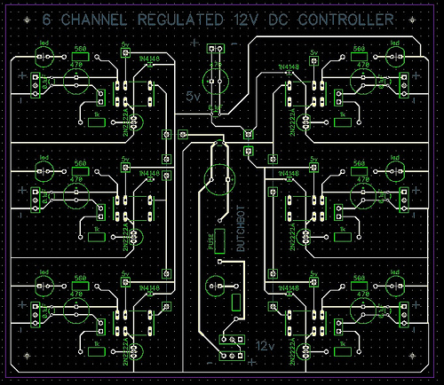
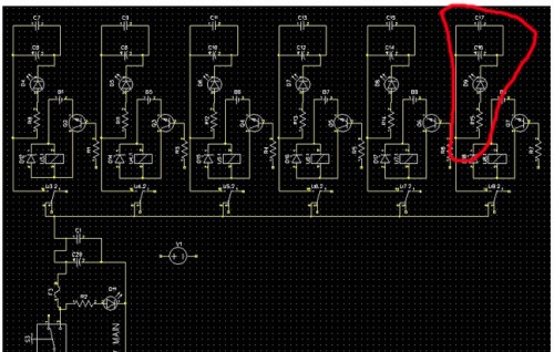
I came up with the below but I'm running into some problems with the traces. Maybe someone can point out the right direction as I think that it must be possible to cross over a line (with some electonic component maybe)? The red circles are the problem areas.
http://flic.kr/p/bo2r8h
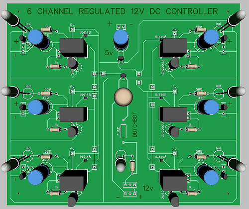
In addition, I'm probably making mistakes since this is my one of my first pcb drawings: Please tell me if I got something wrong. It basically does (or is supposed to do) this: 12v DC goes in, 5v DC goes in, the PIC controls the relay coil at 5v, 6 channels, 6 times 12v switchable (on/off) output. Each relay can handle 1 amp, the fuse is 6 amps. I used oddbot's "regulated power supply" with the 470uF and the 0.10uF capacitors to prevent peaks on any channel. Since it will go on and off frequently i just guessed this was a good plan. For switching the coils I used the 2N2222A transistor with the 1N4148 diode schematic. This kind of sucks as I wanted to run it of 12v all together (and just use the PIC to deliver the 5 volts, but thats a bad idea I read down here). Dropping the voltage and turning the board into a watercooker doesn't attract me so I'm going for an extra powersource (prob some rechargeable cells and maybe a solarcell to keep it full). Maybe I could even use the 12V battery to charge the 5v (4.8v) ones. The latter seems more efficient then using a voltage regulator.
http://flic.kr/p/bAWhHD
Thanks for the advice!
All the best,
Louis
Schematic
Hi OddBot,
Can’t get the flickr photo’s up here but the schematic can be found here (or in the other link posted above):
http://www.flickr.com/photos/75826690@N02/6813044716/in/photostream/
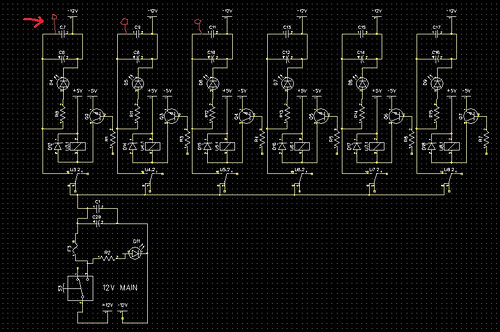
I have used single pins now so I can use a piece of wire to cross the other trace (marked with a dark line).
http://www.flickr.com/photos/75826690@N02/6813044618/in/photostream/
The 0ohm resistor sounds sexier then a piece of wire, I’ll look at that. 
How are you going to make this?
To be honest, you hit this one out of the park in terms of your first board. It really looks great. Few questions though…
First off, it appears you are tying to make a single sided board and your traces are on the top of that board. If you are going to etch this yourself, this is going to be a problem. You will be forced try to solder “under” each part. The underside of your PCB will be blank (no copper at all) and there will simply be no pads to solder to. Also, if this is a hand-etch, you need to almost quadruple the thickness of your traces.
If you are going to etch this, flip your traces to the back, widen everything and you are all set.
If you are going to send this to DorkBot or similar --In that case, you simply need to make a double sided board. Acutally, these places make double sided boards as the “standard” so even with all your traces on the top, there will be corresponding solder pads on the bottom allowing you to solder the parts in normally. Now, if this is indeed the way you are going (a professional PCB place) then your crossed wire thing is as simple as putting the few “offensive” traces on the other side of the board. Done. It is typical to have the traces on one side of the board all go sorta one direction and the traces on the other side go sorta 90 degrees the other way.
Keeping with the professional PCB place idea… If you are going to send this out, you will be paying almost double what you should. This board should be scrunched together by a factor of maybe 30-60%. No matter where you go, it all comes down to square inches of board --and you will pay for each and every sq. in. DorkBot is $5 a square inch as a point of reference.
Make your name bigger. Ain’t no reason not to shout from the rafters… “I made this board!!!”
Beyond that, it does look really great and I will throw in a few more… I personally make my traces about as wide as they can be even if I am going with a profession place. There is simply no reason not to if you have the space. Don’t forget your mounting holes!!! Don’t forget your mounting holes. You are not going to go to all this trouble to design the board and have it made only to stick the bastard down with friggin’ double stick tape! --4 holes in the corners at either 1/8" or 3mm, yo.
I think one of the problems
I think one of the problems is that he has used some SMD diodes that put the traces on the wrong side.
But at DutchBot;
You should try to make your PCB layout in the right order. Make the schematic first and let diptrace help you lay out your board. It might seem like a daunting task but believe me it is well worth the effort.
Start watching the series from: novarm44
http://www.youtube.com/watch?v=VmvC3emkMe8&feature=related …
I had a hard time figuring it out, but at some point it all makes sense
https://www.robotshop.com/letsmakerobots/node/30611
Thanks
Cheers guys, I’m feeling kind of stupid with the layout being on the wrong side of the board :). It made sense to me as I approached this the silly willie’s way. I grabbed a breadboard, stuck on the components and then tried to figure out the best placement (for soldering the bottom together, the drawing as an aid). Soldering as in manual and not sending it out to a pro board maker. Then again Chris, I think I’ll do just that in the end. So I guess it’s back to the drawing board.
OB, sorry m8, pcb layout, schematic it’s all the same to poor old me Didn’t think it was very complex to begin with as there’s really just 2 circuits (times 6) and 2 for power.
Geir, “I had a hard time figuring it out”. Thanks for motivating me, it’s probably impossible to me then ;))) I’ll have a go and let’s see if I can get it right.
What do you guys think of 2 voltage circuits (as in 5 volts and 12 volts) where the 5 volts (std rechargable AA’s) are being charged by the 12 volts? Is that an efficient way to do things? I have seen some charge cut off circuits that could do the job (i think). Again excuse my French, you should see me in the electronics store trying to find components (of which mostly I don’t know the right name). The shop owner already starts smiling when I come in for a game of hints (e.g. I need one of them small blue things that I can solder on a breadboard and has 2 screws so I connect a wire thingy) Back to the batteries, because in the end I just want to charge 1 x 12v lead battery and not the 5 volt one separatly.
Thinking some more
Chris, does it matter on which side the traces are really? I can turn it over and stick the components in the other in way can’t I? Is it just astethics (not having a nice print on the right side) or am I missing something else? Maybe I’ll see it tomorrow, I’m sick at home and can’t focus very well I’m affraid… Being sick at home reminds me of christmas somehow, you know, I’m dreaming of a white christmas. And if I run out of white I’ll grab a bottle of red 
@OB1
OB, man I just googled it, please let me state that I also have to google which polarity the flat side of a led has. Hence, I’m trying. But when this is not a job (i’m an MS engineer; I know Nothing, Google is my Lord and Service Packs are the Solution to All Problems) the symbolism is pretty odd. But yes, you are right, I’m lazy also. Thank you for motivating me. Give me a few days, I think it’s doable. However, I still am tempted to think that the eventual PCB layout remains equally important if not more. I salute you Sir and whish you a good Nap!
Sorry if dampened your
Sorry if dampened your enthusiasm But DipTrace can be a bit hard to get the hang of but the rewards are great, so study the manual and watch the tutorials and you will get there.
I don’t understand why you will use two power sources a 12V and a 5V. Why don’t you just put in a 5V regulator https://www.robotshop.com/letsmakerobots/node/88
@Chris
I just noticed the problem. Bummer Damn relay’s.
Hot
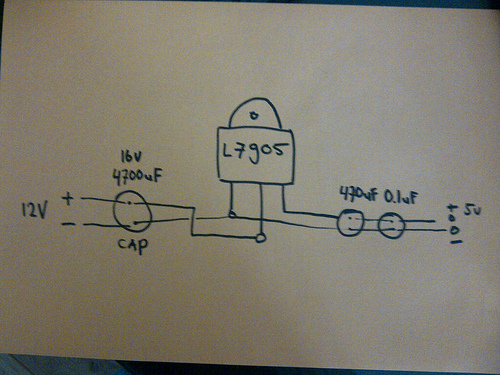
Hi Geir, before this PCB I made a small other one without the software. It’s on here, OddBot’s regulated power supply. I build one without reading it to the end. I used the LM37805 (i think out of my head) and it got burning hot with 12v. So far all the other alternative voltage downgrades just “burned” energy. So why not just load it into a smaller cell and use that. I reconn it’s more efficient to switch off a supply then to downgrade the voltage. Not sure on the losses when “loading”" however.
I do believe that the heat
I do believe that the heat from the voltage regulator depends on the current you draw through it and if the current is only to switch some transistors then I think you will be ok.
But as there is no schematic I have no idea of what is going on
(But don’t take my word on this as I’m a pure armature when it comes to electronics)
Schematic
I tried the diptrace schematics but it’s giving me a headache. I can’t find no pins/headers so I used a bat instead. Now when the thing compiles it into a pcb I get a really strange layout. It’s trowing my control LED’s all over the board with no real logic.
When in the PCB mode I can select a lot more things, in schematic mode they seem missing or have a different name. Phew, hard man.
Good to see that you starting with schematics
What I feel is missing is some power and ground rails. You will find them under Ports_Sch
So if you put in several +5V ports and ground ports all will be connected. You can verify this by holding your cursor over a line and the net will be highlighted.
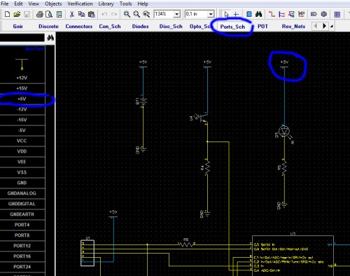
These seems not to be connected to anything but there probably should be a power and ground net connected to it.
You have my sympathy
You have my sympathy DutchBot, but please don’t give up.
I do agree that the hardest part in DipTrace is to find the actual parts and the organization of the components suck. That is why I made my own library and copied all the parts that I have and need in to that library.
Great tips!
Thanks Geir, as always very helpfull tips. I placed the 5v and the 12v supplies on the board now, the red area where you noticed no power should be ok I think. It’s getting its 12v power from the relay (the large vertical strip in the middle supplies that. I added some 12v - poles to the top (to which the solenoid will be connected) but I can’t find something like a 2 hole connector in diptrace (marked with red).
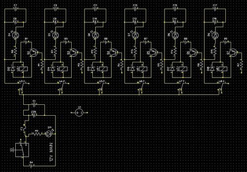
Here is a close up of one of the circuits (6 of them do the same)
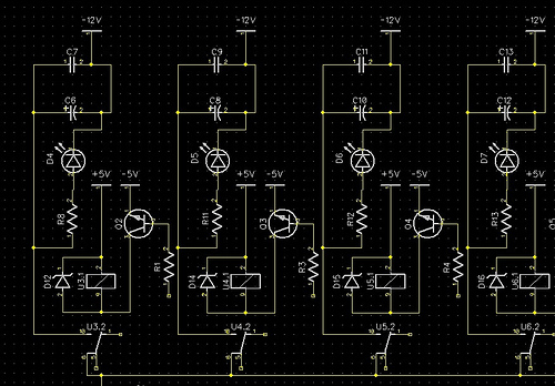
R1, R3 and R4 (1k) etc will connect to the signal wire of the Pic. It should then be able to switch the relay without burning the pin. C6 and C7 are the caps that oddbot used in his regulated power supply (470uF and 0,10uF). The there is an indicator led with a 470 resistor that goes on when the relay gives power. The U3.1 is the solenoid part of the relay, the U3.2 is the part where the power goes in and out.
Must of done it wrong then
I think I did something wrong then, the regulator gets burning hot with no load what so ever. I just looked at it but it seems to be wired correctly.
I sent you an email. So
I sent you an email. So check your inbox and we can take it from there.