I decided to do this as a blog as I plan for this to be a long term test platform as I mess around with different tech along the way.
OK I started by buying this RC truck chassis on eBay:
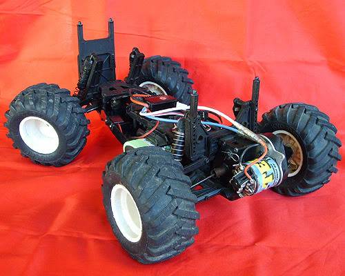
It uses a 7.2v NiMH battery and powers the motor using an ESC that delivers a few AMPs of 6v through a BEC to power a transceiver and the steering servo. Instead of a transceiver, I am hooking up an Arduino Fio and various components, housing them in a project box:
I said earlier that it uses an NiMH battery and you can see a LiPo here. that's because a smart charger and another NiMH battery are on their way and I am waiting to recharge the primary NiMH until I have the smart charger. On the right is a connector I made that can connect up to 3 servos or ESCs. It is connected to one ESC and one servo. Their data lines go to PWM pins on the Fio, the grounds are commoned (as are all grounds in all cases, so I will quit detailing that). The power line has voltage coming in because of the BEC on the ESC and it is 6v. It goes onto the the mini breadboard and is connected to VIN of the Fio. It also powers the "5v" power bus on the second breadboard by going through 2 diodes on the way there.
On the larger (but still fairly small) breadboard, I have a GPS powered at 5v and I run the Fio's 3.3v VCC to power a compass. I currently have a BluetoothMate that I plug into the FTDI on the Fio to receive some simple commands for RC operation so I can see that things work and it reports GPS locations. The compass is I2C and is currently not working. I need to swap it with an identical unit being used on another project to make sure it is good and then psych that out if so.
I have xBee modules that I will do some of my testing with, again wiring to FTDI on the Fio and I have some Nordic chips. It's likely the breadboards will never go away on this unit.
Right now, it will move around as an RC vehicle. As soon as I get the compass working, I have code from another project I need to do some testing with which seeks a potentially changing GPS point (very similar to what Patrick did; in fact it would be even more similar had I found his before I started mine :) ).
Anyway this is my test ground vehicle. I will update as I try various things and hope to add a video as soon as it starts seeking...
with the xBee option installed…
Compass working!
Stupid human! I read this page too fast:
http://arduino.cc/en/Main/ArduinoBoardFio
There is a spot that says:
- I2C: 4 (SDA) and 5 (SCL). Support I2C (TWI) communication using the Wire library.
But before you jump to the conclusion that means the pins labeled 4 & 5, you have to read the text above it:
The Fio has 8 analog inputs, each of which provide 10 bits of resolution (i.e. 1024 different values). The analog inputs measure from ground to Vcc. Additionally, some pins have specialized functionality:
They are the only 2 pins on that page not referred to explicitly as labeled on the board.
Frustrating, but behind me. Hopefully I will test GPS seeking tonight!
Almost ready to post it as a robot
It remote controls as a “regular” RC car fine and it has GPS homing functional (but still needs tweaking). Near term future plan is to put a “lazy susan” style disc on the plate between the front wheels and attach it to the steering servo. That way an ultrasonic mounted there would be able to “look” right or left when I turn the wheels.
A seek test
http://s43.photobucket.com/albums/e396/arbarnhart/robo/?action=view¤t=robotruck-1.mp4
Using the GPS in the unit, it is seeking the GPS in the base (the remote control box).
I started a thread with questions that is turning into a running monologue:
https://www.robotshop.com/letsmakerobots/node/24112
I probably should have just rambled about that here, but I was hoping I might get more discussion starting a thread.
Booya!
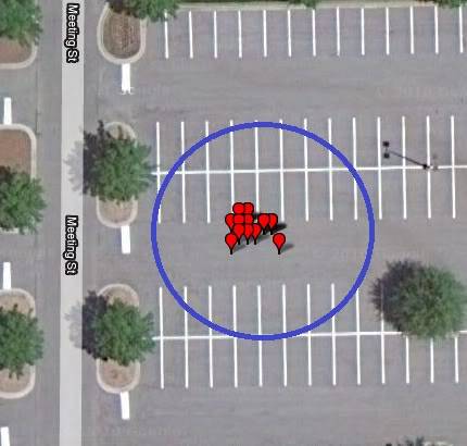
The red markers are locations that the beacon transmitted and the AGV reported as where it was when it went into or came out of a tight slow circle pattern. The blue circle is my observation of the area it stayed within. I had to step out of the way several times. I was able to let it run freely for several minutes without it hitting any of the obstructions, so I think my circle is pretty accurate. I can probably tighten the circle by limiting how many degrees off I allow before forcing a slow turn instead of a slight correction.
I am following your progress
I am following your progress with interest. I have also read (and bought the board) Patrick’s tutorial on his AGV. Finally I asked a friend in Florida to buy for me that cheap GPS, so I will have something to play with in a few weeks. Now I need to find a used truck chassis at Value Village that I can convert for this project. I always wanted to participate in a Robo Magellan type competition, so I guess we can make a challenge where participants can have their own course and video the robot following it. The challenge should follow the rules of the original Robo Magellan competition, so the robot is not remote controlled.
My robot answers to another
My robot answers to another uC - does that count as remote control? The real challenge has been to get 2 GPS units to read the same. I need to take some new pictures. I swapped out the Fio and now have a JK Devices MiniMega 1280 in there. The other project I am sharing code with uses a MEGA 2560 to control a boat and by getting a unit that has the same number of serials and pins I am able to share code better. I have several tabs in each project and they can share most of them. The file for motors is different, the boat has an OpenLog that I don’t have on the AGV and right now the AGV has a “sensors” file that isn’t on the boat, while I try to figure out radio homing to get the last few feet. The boat will hopefully be a commercial product so I can’t say much about it (I am under an NDA with the guy who designed it).
I am trying to home in as quickly as possible, which introduces some other issues, most notably lag time. When you spin quickly, you can’t wait for the exact heading because the motors are not instantaneous. In fact, using an ESC introduces some delay, mostly because of safety features. Another lag time issue is that when you are cruising along pretty good, the GPS coordinates are offset by the distance traveled in the time it takes to transmit and receive them.
Swapped out the brain
Instead of the Fio, I now have a JK Devices MiniMega 1280, which is software compatible to the old Mega 1280 and to the newer Mega 2560 for most projects. I also went to a big breadboard and "real" jumper wires. The breadboard has 4 power buses. On the upper left, power comes in from the 6v BEC and I have a decent size cap because it will surge with motor use. If you look close, you will see that I bridge to the next power bus with a diode so it is only slightly over 5v and use it as my 5v bus. The bottom power buses are not fed now, but will likely be 5 or 3.3v . the compass module has a rep for not liking much power, so it is fed through a diode that puts the input down around 4.5v. The xBee is on a an xBee Explorer, which likes 5v, and the GPS also deals well with 5v. the mini breadboard on the upper left has a 434MHz receiver that I am working with to try to get radio homing for the last few feet. The purposefully weak transmitter for it just sends 'U's at 2400 baud and I count how many in the last 100 characters received to figure whether I am getting closer or further.
the "remote control"
It's another project in itself. That's a Mega 1280 with a LCD, GPS, joystick, compass (I have some ideas for "EZ RC" by mapping the joystick using the way the vehicle is pointed versus the remote) xbee and a little 434 MHz transmitter cause you can never have too many radios. :) Actually, that's not true because it doesn't work very well in there with all the other devices. there is also a beacon that is just a Pro mini, GPA and xBee where the 343 MHz radio will actually go, but for testing this unit is better because I can assume control remotely if things go wrong in autonomous mode.
clarification on what this is
In a Previous post I had this video:
http://s43.photobucket.com/albums/e396/arbarnhart/robo/?action=view¤t=robotruck-1.mp4
of what I consider a partially successful test. I stopped the car a couple of times in the video when I was afraid it would hit something, but it was never running off without turning back. The concept and design works, but I needed to tighten the circle it operates in, and not just to keep it from crashing. When this is used on a boat, it may need to cover all the water inside the smallest area I can accurately determine contains the target. The smaller the area, the less time that will take.
I didn’t do a video this time as I was going alone at daybreak (so I could use a really open lot) and I wanted to be ready to stop the car if things weren’t working. The improvements I made since the video were to go to the first waypoint sent before accepting different waypoints (cut down the jitter in the sending unit), make it go into a slow tight circle anytime it detected that it was very close and to stop and wait for a GPS update if it was using data that wasn’t under a second old. The map above represents what effect those changes had. It still does loop around a lot but that is by design; it doesn’t get to just decide it has arrived; it has to physically encounter the target. I hate using “target” because the main project that I can’t give details on is absolutely NOT a weapon; it is pretty much the opposite. But when it thinks it is close it circles slowly now and the insistence on fresh data keeps it from overshooting quite so far before turning back.
An update on the related project
I have mentioned that I am using this to emulate another project, a boat, that is doing GPS homing. Applying the logic from the AGV improvements I made recently to the USV (aka the boat), it turns out that it needs no other homing technology, but it needs some work in getting on the initial heading without too much starting, stopping and zig zagging. The problem is that pivoting a boat is much more dynamic than an RC car. Operating the car on a flat parking lot is practically like having gears connected to the ground as far being able to repeatably pivot at the same speed and have the same lag time for the steering servo. In other words, through testing yo can come up with a number N such that if you are pivoting and the bearing you want is N degrees away in the direction you are pivoting, setting the servo to point the wheels straight will result in a direction change that will put you on or very near the desired bearing every time (assuming normal power levels; motor speed does fluctuate as that drops). Because of wind, waves and current, this isn’t possible for the USV.
So the next thing I am going to work on is allowing more variance from the desired bearing before I drop into the slow pivot mode.
Now I have sonar!
Ears that are eyes:
A couple of hot glued foam blocks and plastic cover. I glued in wires soldered to a socket for the ping sensor. It is removable. It is fairly narrow beam, good from about 1' out to about 6' for curbs and similar street hazards. For wall, it is more like 1" to 7'. the only thing programmed in for it right now is detection; what to do about it comes next.


