

been looking at these:
http://i531.photobucket.com/albums/dd355/innerbreed/2383.jpg
**
Or to incorporate something like this. i will be constructing it using shapelock.
the following images are “borrowed” from Alan Asbeck and Matt Spenko in there work on the RiSE robot**
Interesting ideas!
Do I detect a small ball joint in the bottom picture? While driving home last night, I was thinking that the foot could be made up from two flat pieces of Delrin or similar material, with a cavity for the ball-end being milled. That would retain the foot on the ball-end rod. The two parts would then be secured together with a pair of screws.
And in looking at your pix, I’m thinking one could have a “skirt” or disk on the stem of the ball end rod to press on three springs. The springs would seat in three shallow holes milled for the purpose in the top piece of the foot.
I think that would do it!
Oh I get it now, use a universal joint, with a spring wrap to make the “ankle” connection! That could work!
Alan KM6VV
just a quick idea here too.
**using the same idea for rc car suspension **
http://i531.photobucket.com/albums/dd355/innerbreed/image003.jpg
i have quickly drawn this up to show how the tibia could allow for a shock absorbing leg.
obviously these parts will be more compact and tight so it doesnt make the leg very long.
http://i531.photobucket.com/albums/dd355/innerbreed/image003-1.jpg
**
with this 'a ball-jointed foot as talked about before would work well too.**
http://i531.photobucket.com/albums/dd355/innerbreed/Capturevhutj.jpg
as i dont have the means to cut my own parts nor have the tools so im searching for the right thing to use.
i have spoken about using servo trays for the tibia and this will also work great for the custom designed bracket seen in my idea.
oh and before you ask why… well all this time off work is getting to me. 
any thoughts?
Interesting idea if you could pull it together a little.
Alan KM6VV
this might be of interest to our discussion on ball jointed foot.
http://www.multiline.com.au/~psanders/images/gps_inst/camera%20mount.jpg
im looking into the right one to use.
That’s the general idea, looks like a base for a camera. a little BIG.
Here’s another idea for a compliant foot:
http://www.marconettengineering.com/BipedLlegsSole.jpg
http://www.marconettengineering.com/BipedSole.jpg
this leg is for a biped, but would be applicable for a quadruped as well.
I like your little R/C shocks, I’ll have to look for some.
If I had more time, I’d further explore the ball-end idea. but this spring-foot could work as well.
I’d like to make it end in a flange to mate up with a servo horn pattern.
Alan KM6VV
Nice. 8)
It does look quite big but its not as big as it looks.
Anyway i have found another one that i will be prototyping when it arrives.
Here i will be using the areas marked yellow:
http://i531.photobucket.com/albums/dd355/innerbreed/foot.jpg
I wont be needing this base as it measures 65mm (to big) as i will be making my own base at about 40mm.
I will remove the top ball and replace with the tibia.
Ill have the two sides that hold this assembly together (brace) 'bolted either side of the tibia.
Ill need to drill some new hole positions in the tibia for this.
Also i will need to add springs (got a box load) from the brace to the base so the foot will return to center each time the foot is lifted. Giving a nice “terrain adaption” effect.
What is the design goal of the new foot?
Good question. 
The short answer…
The design goal for this project is to implement a foot that can engage with better contact on the terrain it encounters.
I wish to study the way in which the foot will react when engaged.
Force sensors will be the next stage!
As the foot will have more contact with the ground I’m thinking it will allow for better control when walking incline.
And also the tibia will only have one single point of contact to the foot, so it wont compromise its performance.
I hope this has answered your question?
What’s the ball and shaft diameter, and the shaft length?
Steel parts? Something easily found?
Alan KM6VV
all i know is:
its rust proof
max mounting weight is 3KG
base diameter 65mm
length (fully extended) 100mm
thread diameter 6mm
you can get them from local security stores, ebay for £1.99 or Google: MOUNTING BRACKET FOR CCTV CAMERA
not yet got my order for the parts, but as im waiting i have done a short vid showing xans great work from his phoenix v2.0.
youtube.com/watch?v=mgktlqBxff8
shortly after this vid was taken i took it back inside and re-calibrated the INIT pos as it wasnt perfect. apart from that im now just waiting for parts.
ok well parts arrived…
but i sent them back… 
the item described was not what they sent. apparently they dont stock that part anymore and the company they get them from upgraded it to the one they sent me, without telling me it was different.
anyway im still searching…
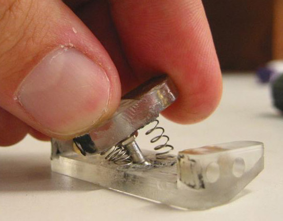
anyone know where i can get a Low fiction Ball joint like this?
http://i531.photobucket.com/albums/dd355/innerbreed/Capturevhutj.jpg
p.s iv already asked matt!
Any bigger picture of that ball joint? Maybe we can work up a drawing?
Alan KM6VV
The foot is attached to the tibia via an 8mm ball (A) which locates into the upper foot socket (B).
This upper foot socket is then attached to the lower foot plate © via two ball joints to form a hinge between (B) & ©.
There is a PCB (D) mounted to the top of (B) which has a micro switch (E) soldered onto it.
There is also a retaining plate (F) screwed to the top of (B) to hold (A) in place.
At the front of (B), there is a M3 grub screw which pre-tensions the micro switch and stops the hinge between (B) & © from opening too far.
The spring between (F) and the tibia base re-aligns the foot when it is not in contact with the ground.
Supplied by Matt Denton.

ISO view

front view

Sounds like a patent application!
Matt has definitely put some thought into this foot. It reminds me of a digitizer probe for CNC. Here the idea is to be compliant in three dimensions, and to open a switch at the slightest contact. Uses switch contacts orientated in a triangle. I might explore that idea more.
What’s the approximate width/length of this foot? Does Matt sell them?
Thanks for the PIX!
Alan KM6VV
it does doesn’t it. all the information given is here so if i find out ill let you know. they are currently not for sale, but i think he is happy for the design to be issued. switch contacts orientated in a triangle is a very clever idea i thought.
a very smart way to make sure there is contact on every step.
i think this design would be quite easy to replicate.
of course not wanting to copy it but the triangle idea should differently be explored.
Looks like it would work great in the dirt, mud and grime of the real world… 
been looking at these.
HD Ball Link w/Lock 4-40(Ea) - Bulk Pack Of 6
http://www.wheelspinmodels.co.uk/products/ripmax/f-sln562_1.jpg
That’s an interesting part. And a good fit of a spring. The spring is often the most difficult part to “design in” on a mechanical project. I hate springs!
Alan KM6VV