Also im working on a caterpillar gait were the two back legs move forward first followed by the middle, than followed by the front. kinda like a wave but with both sides running symmetrical in sequence back to front.
thanks.
once i get a bit more time ill upload a vid.
the ripple gait is very similar to what we alrealy know. im not sure there can be much done with a ripple gait regarding form.
the 25 step gait looks very much the same as the others but with a slight delay between steps.
regarding the TriWave Gait 6 steps “caterpillar”, its still under development but from what i can see the order and transition of the legs are correct. the only problem is its not very stable. i think i need to reverse the order front to back! allowing the gait to move ots COG forward in the first step, making the rest of the gait smoother.
Im still gathering info on the gait genorator but its getting there. just gotta keep playing.
Good work on the double femur. It looks pretty solid!
The gait sounds interesting. I like the idea about having the legs wait between the swings. I’m not quite sure how the tripod gait will work. It looks that the number of legs in the air will be about 3, 2, 1. I’m in for a vid as well
yeah it has really made a difference to its strength.
im planning on changing the tibia with something more sturdy.
TriWave…
the back legs move together then the middle then the front. but ill be reversing the order as i feel it might work better.
again a vid will come soon. i might need reminding tho. very busy. ill try for the weekend.
Looking good!
But I’m wondering why you’ve doubled the tibia? Was it to flexible?
Anyway I would recommend to bend the tibias a little bit together at the end/foot and then use a larger rubber end cap.
With the convenient holes near the foot, I’d be thinking about some sort of ball swivel foot attachment. Add a little spring for passive compliance, and I’m told it’s quite helpful, at least on a 'quad.
I don’t want to spill the joy here but I kinda doubt the double tibia design. It the hex walks the tars twist and rotate on the ground. Giving it double a tibia with two rubber endcaps will only give it more friction. It does look cool though. But I doubt if it is an improvement for movement.
well alan is on the right lines. iv been thinking of ways to attach a foot of some kind.
just looking at options here.
i was looking at using servo trays for this.
you can add another servo (tar) to the bottom end.
zenta has kinda already beaten me on this using ses on his T-Hex, (great work)
although im not looking at add another DOF. More of a passive joint.
im thinking that to use a ball joint i will need to bore out the inner sides of the tibias to “concave” the holes, allowing a better hold on the ball.??
as for the double tibia, its really made it strong, and yes, pulling the tars together would be best. the less contact the better.
Humm, you could make them concave to accept a small ball-end for a foot as you suggest. I was thinking more on the line of a ‘T’ shaped spacer that would give your a vertical rod. The spacer would replace the one you have. The rod would have a ball end on it. Like maybe 3/8" or so. Then the foot could have a cup of some sort. Some simple and light-weight device to capture the ball. A bit of tubing with one end formed over could do this. Or two short plates made concave as you suggest could embrace the ball. I’m thinking of the ball-ends used on DTI’s, mirrors, and other devices in need of a swiveling joint.
Having the ball down on the foot might be desirable. But your idea might be even simpler!
In the case of my 'quad, I have a flange to work with. Let me do some thinking. You too!
been looking at these: http://i531.photobucket.com/albums/dd355/innerbreed/2383.jpg
**
Or to incorporate something like this. i will be constructing it using shapelock.
the following images are “borrowed” from Alan Asbeck and Matt Spenko in there work on the RiSE robot**
Do I detect a small ball joint in the bottom picture? While driving home last night, I was thinking that the foot could be made up from two flat pieces of Delrin or similar material, with a cavity for the ball-end being milled. That would retain the foot on the ball-end rod. The two parts would then be secured together with a pair of screws.
And in looking at your pix, I’m thinking one could have a “skirt” or disk on the stem of the ball end rod to press on three springs. The springs would seat in three shallow holes milled for the purpose in the top piece of the foot.
I think that would do it!
Oh I get it now, use a universal joint, with a spring wrap to make the “ankle” connection! That could work!
as i dont have the means to cut my own parts nor have the tools so im searching for the right thing to use.
i have spoken about using servo trays for the tibia and this will also work great for the custom designed bracket seen in my idea.
oh and before you ask why… well all this time off work is getting to me. any thoughts?
It does look quite big but its not as big as it looks.
Anyway i have found another one that i will be prototyping when it arrives.
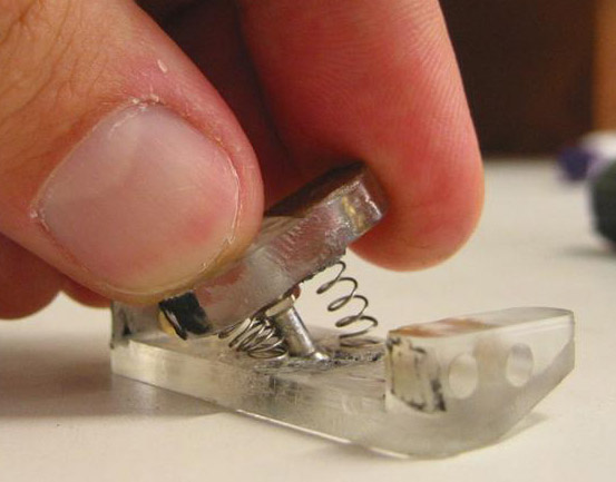
Here i will be using the areas marked yellow:
I wont be needing this base as it measures 65mm (to big) as i will be making my own base at about 40mm.
I will remove the top ball and replace with the tibia.
Ill have the two sides that hold this assembly together (brace) 'bolted either side of the tibia.
Ill need to drill some new hole positions in the tibia for this.
Also i will need to add springs (got a box load) from the brace to the base so the foot will return to center each time the foot is lifted. Giving a nice “terrain adaption” effect.