I was looking at Digi01's Turbot and thinking how cool it was to have a robot that could move and react to stimuli without any software. Some poking around showed me that the original Turbot was a creation of Mark Tilden, the inventor or BEAM robotics.
BEAM stands for Biology, Electronics, Aesthetics, Mechanics. It is a style of robot making that takes it's inspiration from biology. Most BEAM robots are controlled with simple analog circuitry rather than a microcontroller.
Digi01's Turbot used a 74HC240 buffer/inverter IC. I looked around in my parts bin for one, but no luck. I did however have a 74ACT14 Schottky hex inverter. I seemed to recall that you could make some pretty cool circuits with that, so I started hunting around for something.
I decided I want to build a robot with motor and servo control without using a microcontroller. No brain, therefore, 'Mr Loboto'.
Driving a Motor
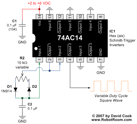
I came across a tutorial on Pulse Width Modulation (PWM) on Dave's Robot Room, which is a very informative site. Dave had instructions for using a 74AC14 (same function as mine, just minor differences) to generate a PWM signal. He then showed how you could use that to drive an LED at different brightnesses and even drive a motor at different speeds. Here's the schematic from Dave's website, with all credit going to him.

I tried it out, and then started messing around with it. I found you could change out the potentiometer for two Light Dependent Resistors (LDRs). One side of each LDR connected to D1 and D2 in the diagram above, and the other sides of both LDRs were joined and connected to pins 2 and 3 of the 74ACT14.
Now I could speed up or slow down the motor by placing my hand over one or the other LDRs. I replaced one LDR with a trim pot, so I could set a threshold for the circuit, and adust the speed with just one LDR.
I built two copies of the circuit and it seemed to work well driving LEDs. I added a transistor driver to each and tried it with motors, with some success. I tried a few values for C2, to try to get good performance with the motors. It's not quite right yet, but I'll keep working on it.
Controlling a Servo
I started thinking about it, and if I could control a motor, I wondered if I could control a servo too. I see lots of BEAM robots, but very few with servos, since you need something to generate the pulse signal for the servo control. I thought if I could use the 74ACT14 to create a PWM signal, perhaps I could drive a servo too!
Some reasearch showed that analog servos need a signal between 30Hz and 50Hz. That means they get a pulse ever 20mS to 33mS. The width of the pulse sets the postion the servo will go to. Servos look for a pulse width between 1.0mS and 2.0mS, with 1.5mS being the center position (1.52mS for some servos).
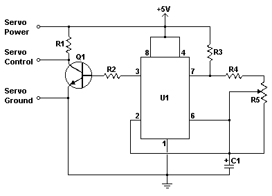
I found this guide on making a simple servo controller based on a 555 timer. I decided to try that instead of the 74ACT14, since I had a 555 lying around anyway. I may go back and try the 74ACT14 later, because it would be nice to do everything on one chip.

R1 = 820 Ohm
R2 = 68 kOhm
R3 = 10 kOhm
R4 = 1 kOhm
R5 = 1K Linear Taper Pot
C1 = 1uF 16V Electrolytic Capacitor
Q1 = 2N3904 NPN Transistor (I subbed a 2N2222, most small signal NPN transistors will do)
U1 = 555 Timer IC
In the circuit diagram above, I replaced the potentiometer with an LDR. I also added a 0.1uF ceramic cap and a 10uF electrolytic cap across the power leads for the servo. This cut down on the jitter due to noise in the signal.
I found the servo had a pretty good range of motion under different light. Using my hand to block the ambient light, I could control the servo position quite well by bringing my hand closer and closer. With the lights dimed, I could use a flashlight to get the servo to move with good control as well. This looks promising.

