Mini Synthesiser 'Allura'

Allura.ASM (13112Bytes)

This is 'Allura' - a small synthesiser I built as a platform to test out a few techniques for another project in progress.

Update 21/2/2010 - I've updated the code again with improved button debouncing and a title animation. There's also a new YouTube video to demonstrate the new modes. The first 3 columns in the top LED rows show you which octave you're in, and the 5 columns after that show you which mode is active. I've just signed up for Vimeo, so there will be an alternative video source for those that can't use YouTube shortly.
Update 20/2/2010 - New version of the code uploaded, implementing 4 new modes that work on any octave: falling notes, rising notes, high speed vibrato and low speed vibrato.

Allura uses a 32mm square 8x8 red LED matrix for optical input and visual feedback. A 5mm red LED acts as a high-precision (compared to fingers anyway) stylus pointer, the light from which is detected by the lower 5 rows of the matrix. The top 3 rows are purely for displaying the status of the device.
Allura makes use of the reverse leakage effect of LEDs to detect where the stylus is pointing, and uses this to determine which note to play. It can play a full octave of 'proper' notes, and by pressing the mode button the octave can be changed from the 5th octave down to the 4th, 3rd or 2nd sequentially. The lever switch on the top-left of the device simply enables the piezo speaker when pressed, allowing the user to slide from note to note, or play them discretely.
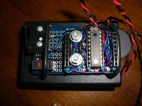
The large black box at the back contains 3 1.5V AA cells, with a power switch on the back. Running at no more than 20mA, the estimated continuous running time of Allura is 135 hours on a new battery set.

CIMG1628_resize.jpg

Unlike many of my projects, Allura only took 1 day to design and build, but much longer to program. I probably would've saved myself a bit of time if I'd checked Wikipedia for info on musical notes before trying to write the code to make it sound good, but we all make mistakes =)
Speaking of mistakes, I managed to 'brick' the first PIC16LF628A I used for Allura. I managed to set a cursed combination of config bits while trying to implement a more accurate timing system. Good thing these guys are so cheap.

This little project is finished for now, but in the future I may upgrade the speaker to something a bit louder (the video is only slightly more quiet than the real thing), and improve the code to allow for more interesting mode options that change the actual sound produced. I've only used 3 out of 255 reserved mode options, so there's plenty of space to program in other 'instruments' if I'm not lazy.

Oh yes, and for those wondering about the name: 'Allura Red' is a synthetic red dye, so it seemed the perfect name for a red light-based synthesiser. Kinda lame, but it rolls off the tongue more easily than 'disodium 6-hydroxy-5-((2-methoxy-5-methyl-4-sulfophenyl)azo)-2-naphthalene-sulfonate'.

https://vimeo.com/9611309

Nice work, Telefox. Do you
Nice work, Telefox. Do you have a circuit (or, at least, a section of the circuit we can ‘times 64’!) I like to see how you are driving, and reading, the LEDs.

I’m curious about those config bits

Hi Telefox

Just wondering how did you set config bits that locked you out of the first pic. Did you set cp on? How do you set the config bits? Do you use the config word with the definitions in the include file? It’s got me puzzled. Interesting project btw.


Oh I just downloaded the code and see you do use the config word. So how did you mess the first pic up?


The circuit is basically

The circuit is basically this one, although I’m controlling mine slightly differently. The PIC has a pin connected to each of the columns (LED positive) via a 130Ω resistor, and a pin connected to each of the rows (LED negative) directly.
If a column’s pin is set to output high, then any LEDs on that column that also have their row pin set to output low will be lit up.

If instead the row pin is set to output high and the column pin is set to output low, the LED becomes reverse biased, and will leak current from the row pin to the column pin, with more current being leaked as more light hits that LED. The column pin is then changed from output low to an input, and also a timer is started. The column pin will eventually go from low to high as current leaks towards it, and the amount of time it takes for this to happen is connected to the light received by the LED. In my program the columns basically race each other, and the first column pin to switch to high is determined to be the one getting the most light, so it must be the column the stylus is pointing to.

Also worth noting is that I’m only running the PIC from the internal oscillator, which is 4MHz. When reverse biasing the LEDs, I found that the column pins were all going high before the micro could even scan them all, because the clock speed was too low. To fix this I only make the row pins high for a few microseconds at the beginning of each scanning routine, which decreases the sensitivity to a level where I can get a reliable reading.

At one point I was using

At one point I was using Timer1 for the SYNTH subroutine, as part of an interrupt service. You may have noticed in the config word that I’ve disabled the !MCLR function on RA5, in order to use it as an input for the mode button.
When I enabled Timer1, I wasn’t really paying attention to the config bits like I should have, and I casually set the T1OSCEN bit.

Now, all that might seem ok by itself, but when you enable the Timer1 oscillator you override any other TRISB settings for RB6 and RB7, forcing them to be inputs for the oscillator sync. Between the !MCLR, PGC and PGD pins all being tampered with, I could no longer access the PIC via my PICKIT2…
To be honest even after I looked into the problem I thought that the ICSP routine would’ve still been able to put the PIC into programming mode, so it’s possible that it’s just a coincidence, and it was something else that stopped my PIC from responding. The PIC still worked by the way, I just could no longer access it for reprogramming.

I’ll have to look at the programming model again

While I hear avr users getting into strife locking themselves out by setting fuses wrong I didn’t think that was possible with the pic because of the 2 voltage levels used when programming them. It’s not just that the pgd and pgc lines aren’t isolated when you program is it. Have you tried changing between lvp and hvp in mplab. Disconnecting and reconnecting your board and programmer.

What message do you get from mplab when you try to program that pic? I’ve thought that I’d stuffed some in the past and then found that they were ok. In fact I haven’t lost a pic yet one way or the other. They’re pretty tuff.

Amazing! I wish I could
Amazing! I wish I could build stuff like that! Still havent made my 1 year old 8. LED number display do anything :slight_smile:

I didn’t think it was

I didn’t think it was possible myself, but one way or another the chip had decided it didn’t want to play anymore. Whenever MPLAB tried to set the micro to program/verify mode, the chip wouldn’t respond with the correct part ID (just 0x0000), and so MPLAB would cut the connection. At first I thought it was a wiring issue, or some grit in the programming sockets, but even removing the PIC and putting it in my ZIF socket programmer yielded the same result.

I used to have an old Velleman PIC programmer board which didn’t support proper HVP, and as such if you turned !MCLR off you’d no longer be able to reprogram the micro. Even now that I’ve got a PICKIT2 I always use HVP for convenience.

At least your accident is a lesson for me
Sounds like you covered it all then. Bad luck. Can’t beat pickit2 for ease of use hey.

New video added, also
New video added, also uploaded to Vimeo as an alternative for the YouTube-impaired.