mini ir beacon

38khz_code.bas (3861Bytes)
beacon_test_tracker_use_ctc_method.bas (2483Bytes)
beacon_test_tracker_use_ctc_method_0.bas (2903Bytes)

So this is the mini ir beacon I've had mulling around but never got around to building one....or finally built it. I'll post the current code for this in a bit.

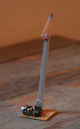
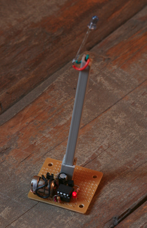
The circuit is pretty basic in that it just uses a picaxe, an ir emitter, led, some resistors and a npn transistor. Ialso wanted to keep it small(hence the mini) so decided to use some lr44 batteries to get around 4.5v out. The battery holder was fashioned out of some 18ga colid copper wire which does a great job of holding things together.

The setup

pin 2 of the picaxe goes to the collector and this is the where the 38khz carrier comes from

pin 1 is the serial data that goes to the base. There is also a led connected to the base so any signal that goes out causes it to blink.

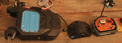
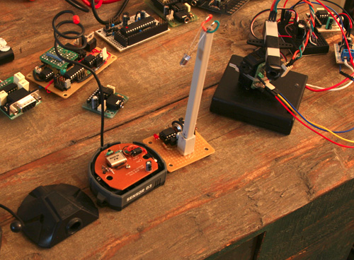
The main ir extender uses a 2 pin m to f connector at the bas of the unit so I can easily remove it and modify it for other purposes.

Expanding on the system to utilize the rest of the axe options to make it configurable.

I plan to expand this to take advantage of the other couple pins that aren't in use. pin 3 will be used as a simple button input.

pin 4 will be used to tune serial signal via adc input and based on a set of predefined strings that I will want to send out.

The application flow would be something like so: turn on beacon, have a delay that waits to see if it will be tuned(input 3 is triggered). if not, read variable in stored memory to find out what signal to output. go to beacon mode.

if 3 is triggered read stored memory and output the current beacon setting.

when 3 is triggered again, this sets the config mode.

read adc and output blinks from pin 1 to let user know which beacon definition the proc is configured to.

when this is set trigger input 3 again to set the beacon output string to memory. go to beacon mode.

the setup switch and dial to set the beacon will mounted on a small perfboard so as to be used on multiple beacons.

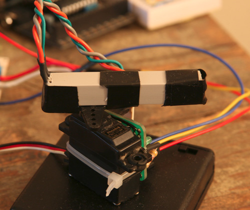
images of the beacon so far.

mini_beacon02.jpg

mini_beacon01.jpg


Edit:

I have the receiver side as well, which be be another post later.

To expand a little more, the configurable ones could be set in a different room/location while (dummy)beacons using 555/556 timers can be set in the room/location to help in triangulation. These should be simpler and cheaper to build.


Edit 5/24: -code update -see new post

Edit 5/25 -code update -see new post file size 2.83k

Edit 6/14 - added video of ir beacon and receiver in action.

https://www.youtube.com/watch?v=pBdXmc34Rk4

looks awesome, cant wait to
looks awesome, cant wait to see this in action with a tracker or something. Keep us updated

could the ir reciver on a
could the ir reciver on a picaxe 28x1 detect this becon?

yes
yes

yes

Yes, and I actually run another 08m on the receiver side but any proc can be used(I’ve used an arduino and bs2 already as tests). I’ll post a schematic of this along with the code that I’ve used. I have I have not written the expanded code that I mentioned above for configuring the devices, but I figure that’ll be pretty easy to do.

I’m currently working on a receiver end and tracking the ir beacon though not successfully…I think I mayhave made it overly complex… :confused:

I’m going to work with ctc’s code to see if I can get better results.

i was planing on having 4 or
i was planing on having 4 or 5 "fake" and 1 "real" beacon hiden arround the house for my robot to find and your desing is very compact so it would be perfect if i can get it to work!

This is a link to the other

This is a link to the other sub project that I worked on to use the ir beacon. This is when I was working with ctc to get some wireless stuff up and running.

I posted the code there.

The 38khz code 2 file is the ir beacon code. I’ve tried to get as much commented as possible so people could understand it. Let me know if you have any questions on it.

I have to note that the timing and that first high low high prior to sending out the signal seemed to improve overall readings though I think this is due to the fact that I’m using an interupt to detect the serial signal on the receiver end, so this would be a hello, then I 'd read the input.

The bt test file is the receiver end of things, though I have to note that I modified it heavily due to needing to use a servo to do directional location, one area being the frequency as I was using 8mhz which didn’t jive with other components I was working with. but this will give you an idea of what you need to do.

I’ll post the modified version when I have it improved as I’m still not happy with it.


EDIT: also if you have any material on how you’re going to make the dummy ones, I’d love to check it out. I have some ideas…but never hurts to see what others might use as well. For mine I currently plan to use a 555 or a 556 dual timer chip as they seem to be the most basic out there. :smiley:

Thanks ! for the moment I

Thanks ! for the moment I wont be able to work on them because the total off all the parts is a bit high! and it is nearing the en of the school year so that means tests !

I didnt know much about 555 timers but got some info on them from a post on LMR, and for my project they wont work because they can only emit IR signal (at least i think).

I was planing on mounting an IR receiver to a servo on top of my robot so that it could find an IR source comming from a certan dirrection, like CTC’s Free Range Robots (IR Beacon). The difference is that my robot will hopefully be able to emmit an IR signal as well( dont know how yet ).

What will happen is when the robot find and IR singnal from one of the beacons, if it isnt the right code comming from the beacon my robot will send an IR signal to turn it off and contunue looking for the “real” one that will later, if i am able to, become a charging base.

just for the record, I’m

just for the record, I’m lookin at using the 555/556 to generate the 38khz carrier signal. I’ll send a seperate pulse on that carrier.

I’ll post the ir receiver setup that I have as it’s what you are discribing. :smiley:

I’m was looking at doing something very similar to what you are talking about, though my concern is the power requiriments, but I may have that figured out…

I got this little toy sort of trigger sensor it’s like an intrusion sensor that when set off sends a signal to the base station. I took one of the 3 sensors appart and figured I could use these three sensors as way points.I wanted to put an emmiter and receiver on each of these waypoints but remove the actual sensor and just use thethe transmitter inside. The base station I would hook up to another microproc that would be connected to a computer and let me know at which waypoint the bot was at

The plan was to have the waypoint send out a a constant signal that the bot would home in on. when the signal strenth was high enough, the bot would let the waypoint know it was close. then go to the next one. It’s quite similar to what you are talking about. I think I put it in a post a while back…just haven’t gotten to it yet…aside from taking the waypoint device apart. :smiley:

since I have a bs2 homework board I figured I’d hook that up to the base station side…I put pics of this stuff up as well.


Here are the parts.

base_plus_waypoint.jpg

Above is the base statio(note the 3 leds onthe bottom)each of the way points(right side exposed)transmit and can trigger one of the three channels. I canpic that up via digital pin to know which was triggered.

beacon_plus_otherparts.jpg

I tried to make the ir beacon board(or mounted components) small enough to fit inside the waypoint.


beacon_seeker_1.jpg

This is the ir seeker mounted on a servo.

The board side of the seeker

Thanks for the pics! I looks

Thanks for the pics! I looks like you are way ahead.

I was worried about the power requiriments aswell, I think I might have the beacon go into sleep or hibernate or some other form of cutting power to the chip after it receives a comand from the robot.

I’m going to do the typical,

I’m going to do the typical, brown out detection off and a couple other things to try and conserve power. I haven’t checked the power consumption of the beacon just as a standalone sender without the receiver or anything else hooked up but I expect it to be low. I’ve had the beacon running for a 24hour period so far to see if it would last through a day and so far so good. I dont run any resistor on the ir emmiter since it’s running though the pwm and only gets hit when I send the l/h/l signal and serial out. I don’t think this is enough to fry it and I’ve meant to add a low 30-80ohm resistor at some point. I do however plan to have 2 emitters and up to three for a tri directional beacon. for those I’ll be using a 30-80 ohm resistor.

For the receiver I plan to use the same trick of using the interrupt to trigger the reading of a signal. This should also preserve power.

Just another note, I’m running the beacon on the lr44 button cells…nice and small but yeah, they’ll only last so long. End goal for this is to use rechargeable cells, nimh and solar power to charge it through the day…I know this is a tall order for all of this stuff…but still,when I start projects I do big projects. :smiley:

Now go ahead and ask me what the big project is that i plan to use all of this on and I’ll tell ya about a small plot of land I have in the desert that I plan on doing some experiments with. I actually plan to open it up to other roboteers for the big project.

You could say this is my local global lmr project.

Added updated version of

Added updated version of beacon code and the lastest seeker code.

The seeker code is a complete rewrite that started using ctc’s code but became it’s own beast through testing. I ran into some interesting issues while writing this code, one being when doing a pulsin seemed to cause issues with further attempts at reading the ir signal(serin part of it). I commented this in the code as such. I think I worked around the issue, but not totally convinced as of yet.

I use pulsin to solve the issue of checking to see if the pin is in a low state , as just checking if the pin is low can miss the high/low state and just keep scanning…at least this is what I found. The pulsin seems to be a nice mix as the ir beacon blinks long enough to detect the high state.

I also tried the “lookdown” function(very cool btw) for comparing what ir beacon I’m looking at. this vaule will later be used in a select/case code block.

There are a lot of timing issues which again I have tried to get around through adding pauses throughout the code.

added int code to mid sweep

added int code to mid sweep points to pic up more beacons just in case.

now outputs to serial, can be commented out if necessary.

Added some code that helps to smooth out the setfreq command and how it causes spikes in the servo.
Adding a cap also smoothed it somewhat but the spike mostly persisted.

cleaned up code after inital pulsin. added a low/high command which didn’t affect the current functionality but made more sense as the pin is active low.

Video post of ir beacon in
Video post of ir beacon in action with two beacons. The intermitent stoping is due to the ir signal being detected and read(see code for full understanding of whats going on). This is due to the small angle which is being viewed by the sensor. I’m considering testing this with a wider angle as the data reads can be somewhat inconsistant. This issue may also be due to the ir beacons not having a long range unless made more direction(and adding more emmitters).

Thanks! :slight_smile: 1. can’t always

Thanks! :slight_smile:

1. can’t always see the laser

2. Already done. when looking at the second part of the video(top down), you may notice a green led blink(front left side of servo). thats indicating it’s getting the signal.