

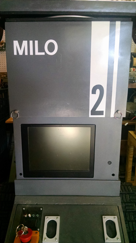
MILO is the successor build to ScoutBot 1402, and re-uses many of the components from that robot. Since he is the second attempt at a large robot, there is a "2" on his torso.
MILO's chassis design was greatly influenced by the many, many things which DID NOT WORK WELL with the ScoutBot. Just some of the changes/improvements are:
- Track configuration that is less "tank like" and more "bulldozer like"
- A Torso that can "shrink" by 9 inches in height, to lower CG for going up/down loading ramps
- A "ball turret" head design that is lighter and more stable than the ScoutBot head"
- Over-all lightening of materials, to reduce upper weight and lower the CG
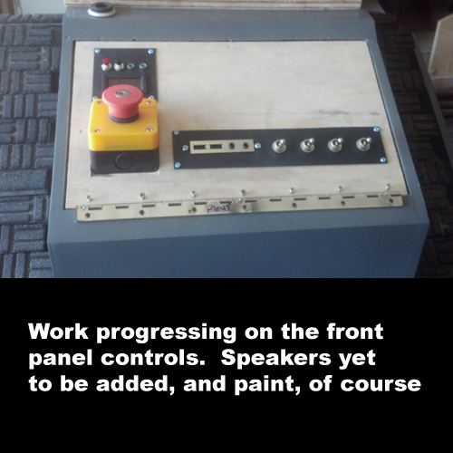
- Accessible front panel switches to isolate sections electrically, in the event of "crazy behavior"
- and more...
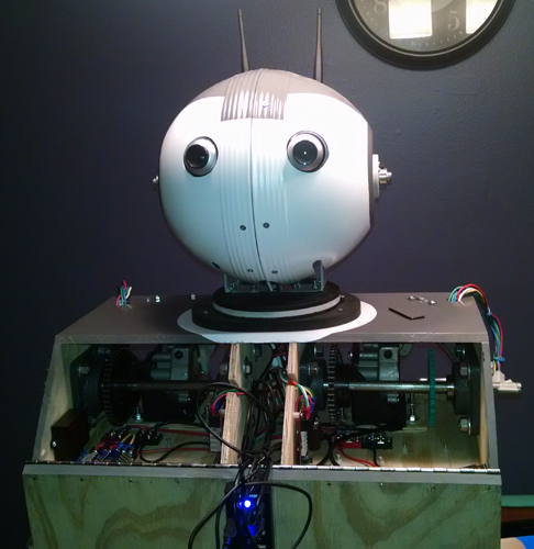
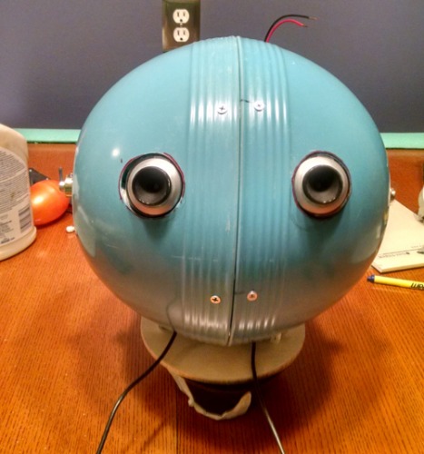
The main photo is from my son's recent HS Graduation party, where MILO sat in our front driveway, and greated guests with one of 21 randomly generated phrases programmed specifically for the party. Guests were quite amused.
As it is a continous work in progress, things change over time.
I will work on getting some construction specific photos uploaded, so you can see the techniques and materials used in the build.
From the "bottom up"...
THE DRIVE UNIT:
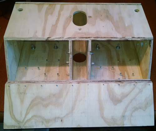
The drive unit pretty much houses everything that makes MILO a real robot. There are the twin batteries, PC Power supply, CPU Motherboard and SSD, Primary Drive Motors and Controller, a forward facing navigaional webcam, audio speakers and front panel controls. Basically, everything ABOVE the drive unit is just a "plug in accessory".
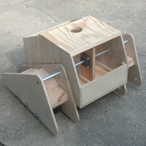
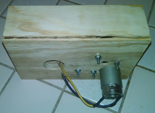
Here is a rear view of the drive section while it is still bare 1/2 inch thick plywood:
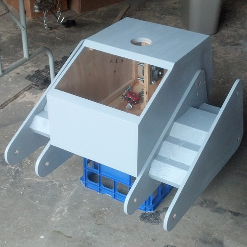
After a coat of grey primer:
The PC Power supply mounts vertically just in front of the dual wheelchair batteries:
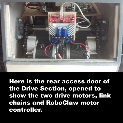
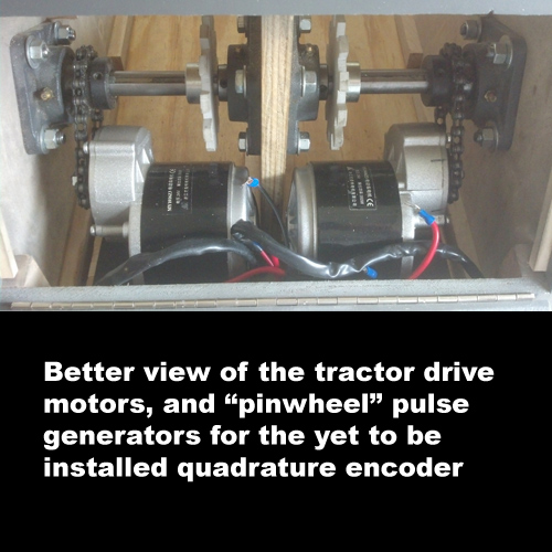
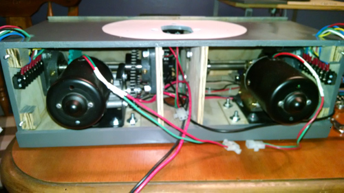
Rear panel open to show drive motors and controller
*** UPDATE ***
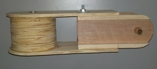
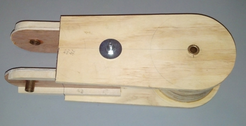
So, I needed to install the mechanical rotor encoders for the primary drive shafts, which means that I had to disassemble the drive shafts. Ugh. I hate that. I mean I really hate doing that. So, before I was going to do all that icky mechanical disassembly, I wanted to make sure that the encoders and gearing were going to fit THE FIRST TIME. Here is what I did:
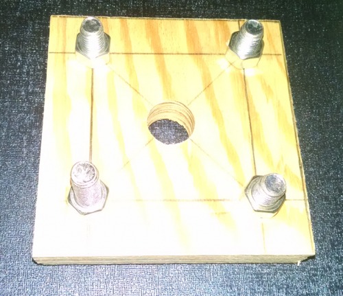
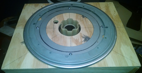
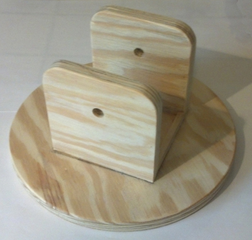
Using a piece of scrap plywood, I made a bolt pattern template that exactly matched the drive shaft bearing, down to the 3/4 inch hole in the center for the shaft. Using this, and a leftover piece of the shaft, I was able to test fit the aluminum bracket I made to hold the encoder at the proper distance for the connecting gear:
Using this test fitting jig, I was able to fiddle and finangle with the bracket and mounting holes until I got the exact fit I was looking for.
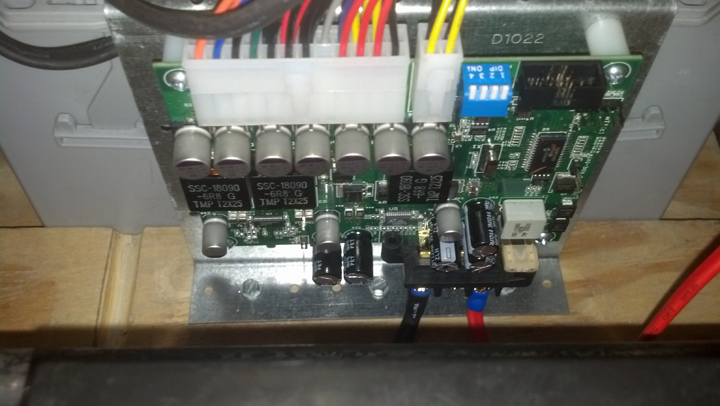
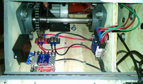
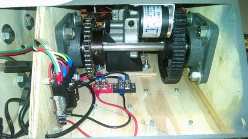
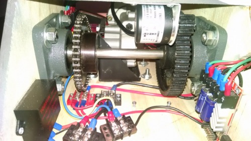
Here is a shot of the brackets and encoders mounted in MILO's drive section, along with the wiring for the RoboClaw controller inputs. You'll no doubt notice that the big "pinwheels" are gone, as I am no longer going to try to scratch build quad encoders, when I can get them for 12 bucks each now, with a higher PPR than I could ever hope to make.
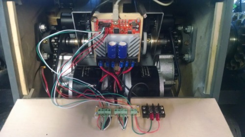
Also, take notice of a two position wiring block (the black terminals to the right of the interface board). These are set to go to the E-Stop switch on the RoboClaw controller. I tested all these under software control, and everything looks good. At full speed (which is faster than I can run) the Drive Encoders put out 13000 pulses per second. I should have plenty of resolution for speed and position. I plan on installing a spring action set of bumpers on MILO while the drive section is on the work bench. Limit switches in the bumpers will be wired to the E-Stop Block above, to make MILO halt if he bumps into something unexpectedly.
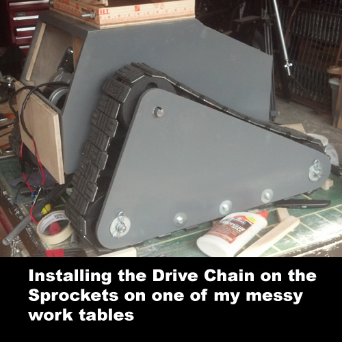
The tractor drive chains are made from segments of REXNORD conveyor belt roller chain, in my case a mix of 4.5 inch and 3 inch chain. It is schedule 60, which is really, really heavy and beefy.
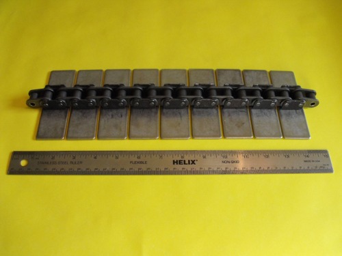
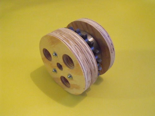
The corresponding sprockets are also very heavy. I used my router to machine out perfect spacer circles to attach to the sprockets to support the drive chain, side to side.
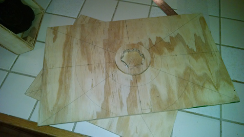
Since I had fixed lengths of chain, reused from the ScoutBot, but I wanted a different tractor drive configuration for better stability, I created a template which let me experiment to find the proper spacing for the sprockets and idlers:
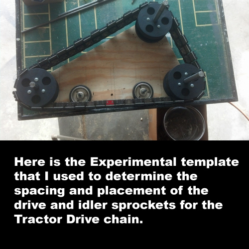
After determining the proper locations for the chain axles, I could then complete the tractor drive "outriggers":
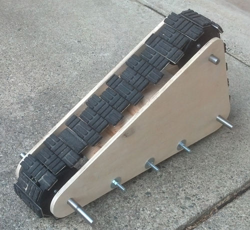
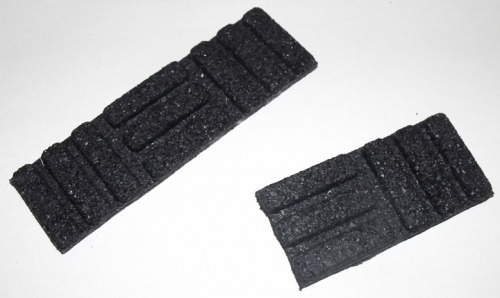
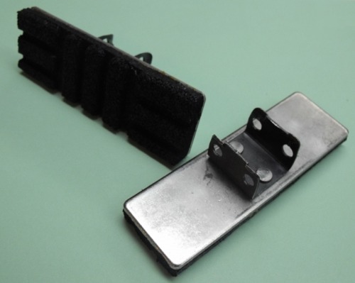
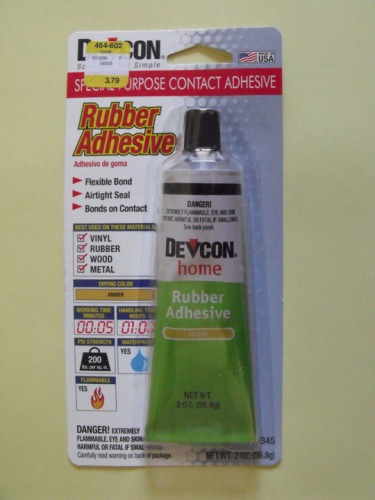
I purchased a doormat at Home Depot that was made from recycled tire rubber. I cut it into sections that would fit on the stainless steel plates, and glued them on with rubber cement.
(more content goes here)
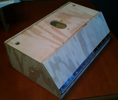
THE TORSO:
The torso is basically a pair of telescoping hollow boxes, held together with pull out pins. In the primary photo above, the torso is in the the fully extended position. When MILO has to navigate a steep grade (such as being loaded onto his trailer up a ramp) or if we want MILO to perform tasks at a "table top" level, the pins can be pulled, and the torso will "collapse" by 9 inches. This also covers the LCD panel, making it safer to transport.
(more content goes here)
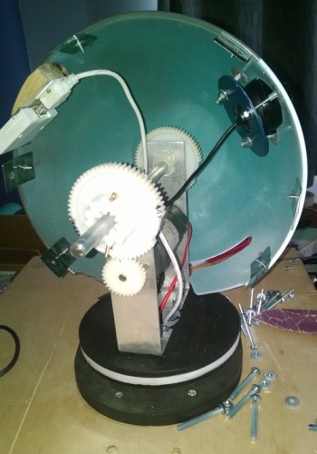
THE SHOULDER:
The shoulder is quite a complicated bit of mechanial work. Not only must it swivel, it must not allow wires to get tangled and house the motors, shafts and bearings for swinging the arms, it must also house the electronics to control the arms, head and webcams. Oh, and it also must have enough room to get my fat fingers in there to work on it. Whew!
We begin by building a housing to mount a garbage picked Power Wheels car transmission, so the shoulder can swivel.
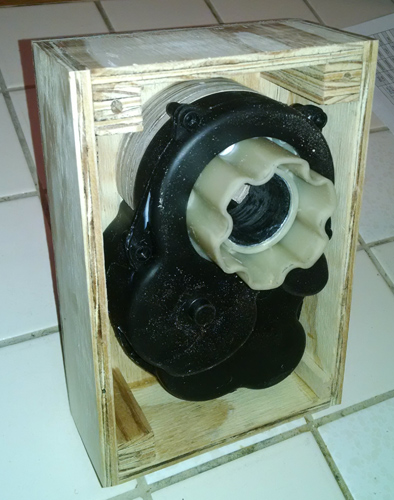
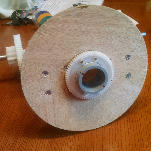
Here we can see how the undermounted transmission has the spline shaft poking through at the center of the Lazy Susan bearing.
This Lazy Susan bearing is rated for 300 pounds, and when loaded with the head, shoulder and arms, spins very smoothly and with little effort. The Power Wheels transmission is more than adequate to spin it.
Next, we make the "receiver spline" fitting, on the center of the panel that mounts to the TOP of the Lazy Susan bearing.
It is a little hard to make out in the photo, sorry.
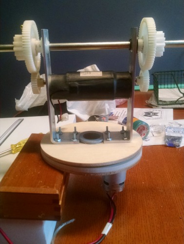
*** UPDATE ***
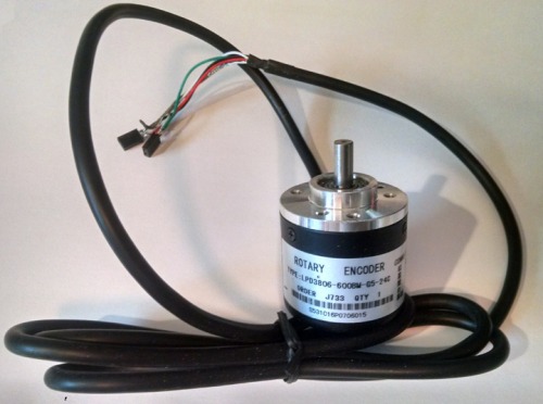
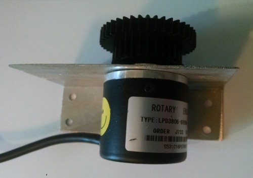
So, I ordered a dozen of these SWEET encoders thru Amazon. They cost about 12 bucks a pop. Yeah, they are all made in China. However, they provide 2400 pulses per revolution when they are connected to the RoboClaw motor controllers, so that will offer more than enough precision of measurement for position control for the various axes of MILO.
The issue of course, is to mechanically connect the encoder to some axis that the robot is moving. I decided to start with the SECOND WORSE case, and that is the SHOULDER. From the photos above, you can see that MILO's shoulder is driven by a Power Wheels transmission, wholely contained in a small plywood mounting box. The transmission is sealed, and what is accessible for the motor drive does not have sufficient "mounting" possibilities. So, I had to disassemble a lot of MILO to get to the shoulder transmission for modifcations.
![]()
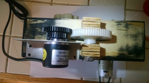
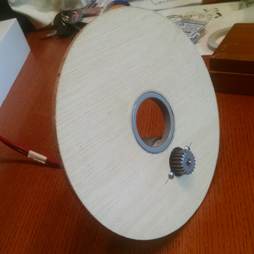
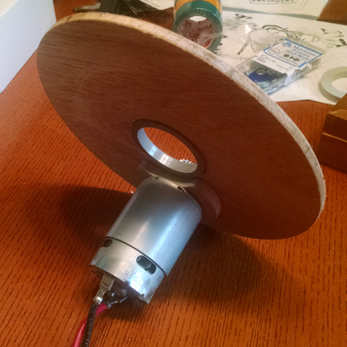
I determined which gear INSIDE the transmission was CLOSEST to the mounting box. I removed transmission and disassembled it, then used a Dremel Tool to CUT A SLOT in the side of the case, exposing the gear. I then cut a corresponding slot in the transmission mounting box. I sanded the side to expose bare plywood for the purposes of gluing the two cleats you see there that will support the axle for the gear I will add...
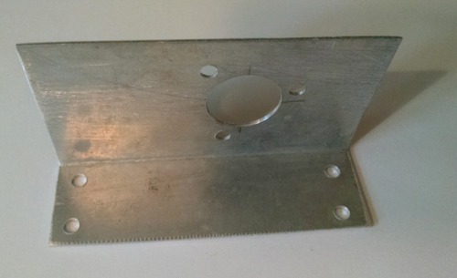
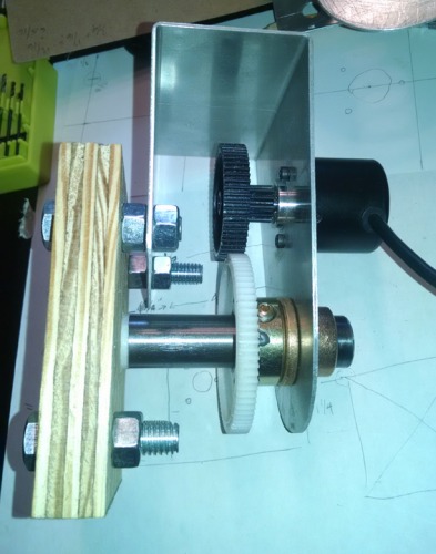
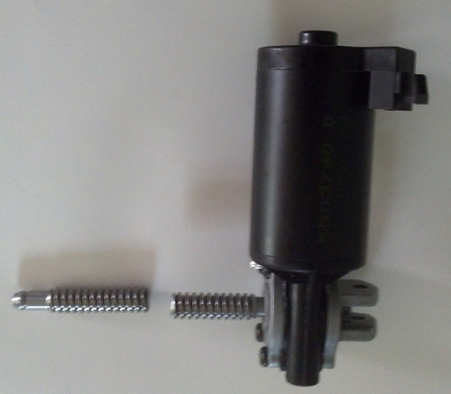
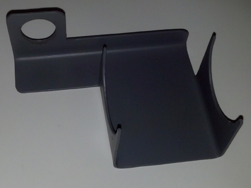
I made a simple bracket for the Encoder, as shown above...
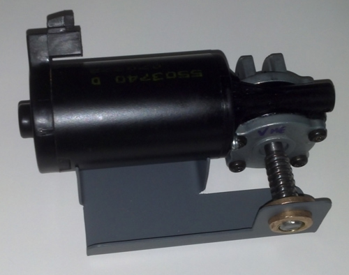
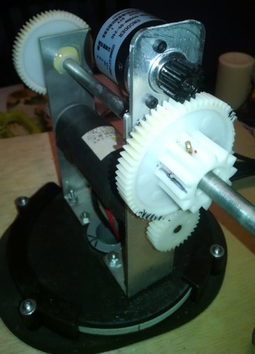
Here is the encoder along with a compatible toothed gear I purchased from SURPLUS SHED...
And here is a photo of the test fitting, along with the gear which engages BOTH the interior transmission and the exterior encoder.
When I am happy with the smoothness of operation, I will repaint the pieces, even though you don't see them as they are buried in MILO's upper torso.
I will directly mount the RoboClaw controller on the outer box, along with the small interface board I have to make, since the encoders require a "pull up" resistor in order for the RoboClaw to read their pulses. Once this is done, it will go back into MILO's torso, and will begin figuring out appropriate PID settings for position control.
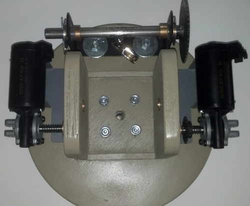
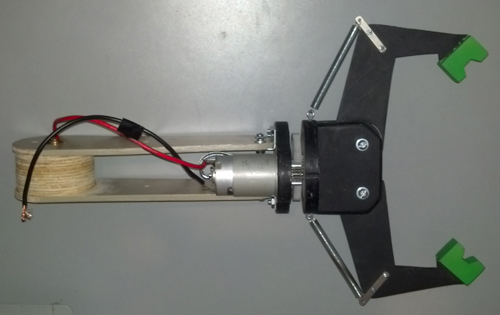
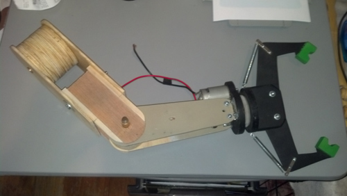
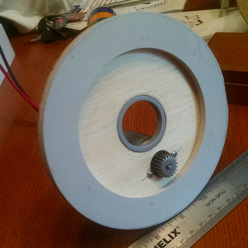
Well, the transmission for the shoulder is finished, and fully wired and tested under computer control. I was VERY pleased with the results. Here are some views of the transmission from the top and bottom:
Here is the transmission installed in the upper portion of MILO's torso:
![]()
Now there are only two external connections, the 24V power line and the USB communications for the RoboClaw controller.
The encoder outputs needed pull up resistors in order for the RoboClaw to register the pulses, so that is what the bottom mounted interface circuit board is for. All connections are such that individual sub components can be isolated and removed for service.
So that the shoulder cabinet can be removed for maintenance without messing with the swivel mounts, it is made as a separate piece, attached with 4 quarter-twenty bolts.
Here it is ready for sanding and painting, and then to have mechanical and electronic components stuffed in...
A shot of the arm "swing" motor for the right arm...
A look at the motors mounted from the rear.
*** UPDATE ***
I continued with installation of rotary encoders with the shoulder arm shafts. I ripped out the largest gear from a Power Wheels transmission, and cut out the smallest mating spur gear from the same transmission. This gave me a 6:1 ratio, so that the encoder will spin 6 times for each arm rotation. Since the arms cannot really rotate 360 degrees, this 6:1 ratio was important so that I could get at least 3 spins on the encoder for decent position resolution.
Here are some photos of the encoders, mounted on the underside of the TOP of the shoulder enclosure.
The LEFT arm:
The RIGHT Arm:
In the photo above you will see where I have temporary terminal blocks, so that wires that ran to a previously removed controller board are not just dangling in space to cause shorts.
As of this writing, I have not completed the interface board with the pull up resisters to send the signals to the controller. Maybe next weekend?
Here is the Shoulder with head attached.
(additional content goes here)
THE ARMS:
With the exception of starting new "hands and fingers", the arms are a direct lift from the ScoutBot build.
The "base" of the arm would be the shoulder mount, shown below in all its bare plywood glory:
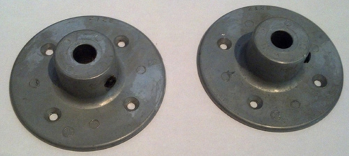
I wanted a design such that I could easily remove and replace the arm, with a fairly common 1/2" shaft hub mount, so one of these each are on the back of the shoulder base shown above.
For the arms to be detachable, all the motors that drive the shoulder lift, elbow lift, wrist rotation and gripper open should be on the arm itself. Since the every motion except wrist rotation is cable driven, that presented some challenges. Using surplus automotive seat positioning motors, I began by cutting off the excess shaft.
I designed a single piece mount that I could cut out of sheet metal and fold up using my metal brake.
Here is the motor now in the mount. Two of these on each shoulder mount drive the shoulder and elbow lift motions.
On the shoulder mount, with other pulley drive hardware:
The upper arm segment is attached to the shoulder mount. Here are two views
The lower arm segment, with the gripper attached, looks like this:
The completed arm assembly looks like this:
(content goes here)
NEW FINGERS AND HANDS:
These have been started, and are far enough along to show the basic finger operation, although I have not yet finalized the actual "wrist" configuration yet.
Here we have some 1/8" plywood, and I am using my cheesy trick of simply printing out a cutting pattern with my laser printer, then using diluted Elmer's glue, I stick the patterns directly onto the wood sheets. Then I use the scroll saw my lovely wife got me for Christmas, and I cut out all the pieces by hand.
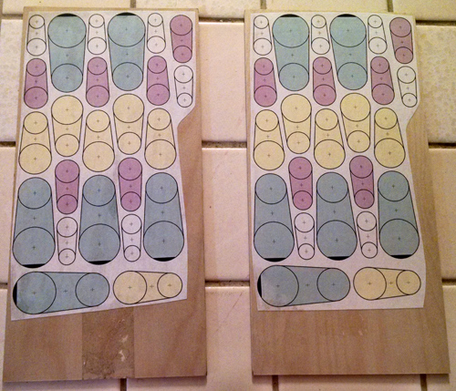
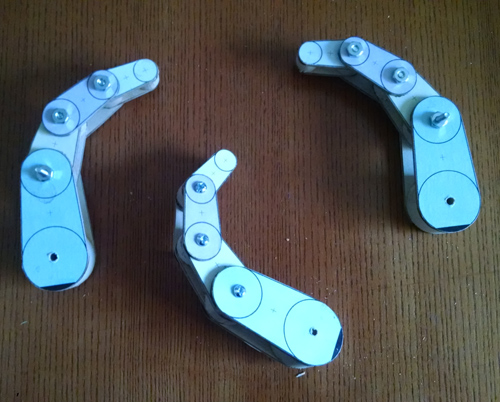
Here is a "set" for one half of a finger. Each segment takes two of these pieces.
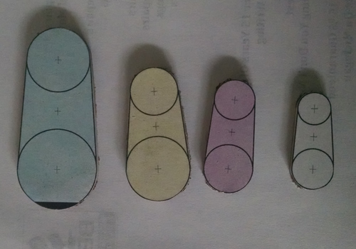
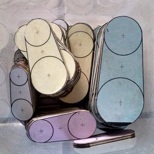
Here are the bowl full of pieces I cut to make a total of 6 fingers.
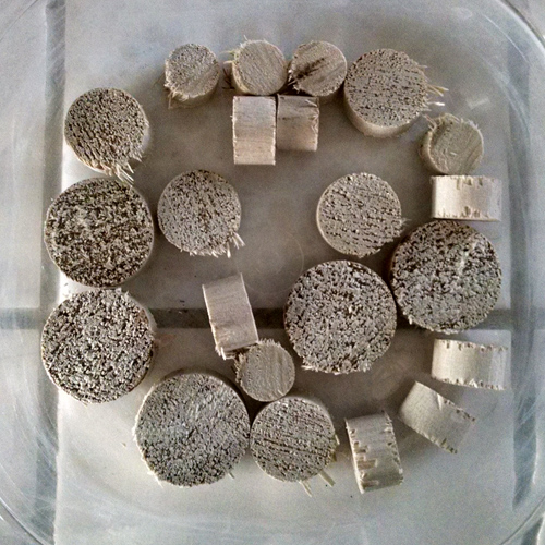
I cut spacer segments out of different diameter dowel rods, also tossed in a bowl awaiting assembly.
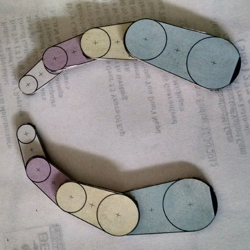
Here is a test go round with some segment pieces. Take note of the circles with the + in the center. Those will become the pivot points of the joints. Notice the other + markings. Those will be drilled to accept a small, smooth nail, to serve as a pivot point for the line that acts as the constricting "muscle" for the finger, as well as attaching points for the springs that hold the fingers "open" when the line is relaxed.
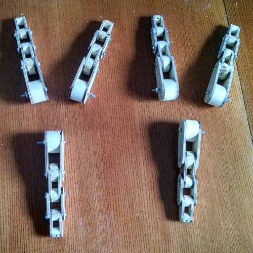
A test fit with bolts after drilling. Pictured from the side.
A test fit with bolts after drilling. Pictured from the top.
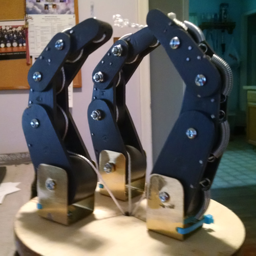
Here is a "testing rig" I have made, to check out the action of the fingers, and to discover what angles I can set the mounting brackets at to achieve a good balance between open/close action and object gripping. There is a fair amount of trial and error about this. Take note of the springs you can now see at the "knuckles".
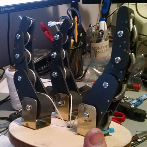
All three lines of "muscles" run through the center of the "wrist", and are intended to be pulled at the same time. Here you can see the fingers beginning to "curl" around. It is neat to put an object, like a Coke can, and see the fingers wrap themselves around it.
It will still be a while before Milo gets these new fingers and hands.
(content goes here)
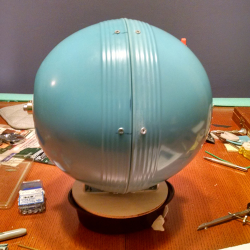
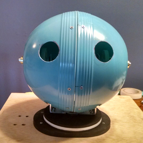
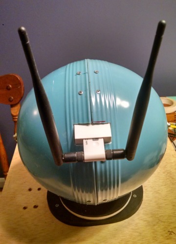
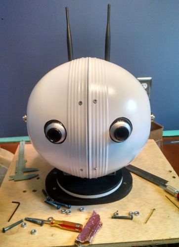
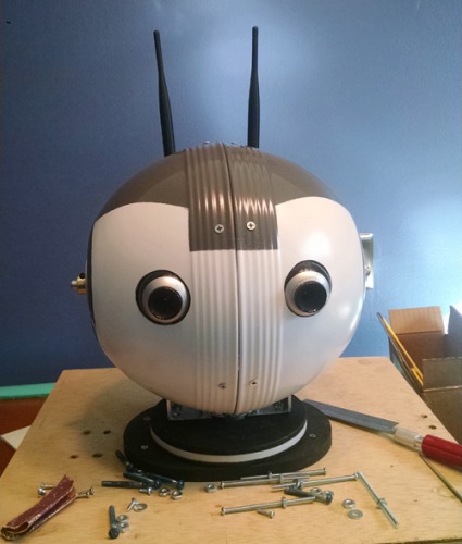
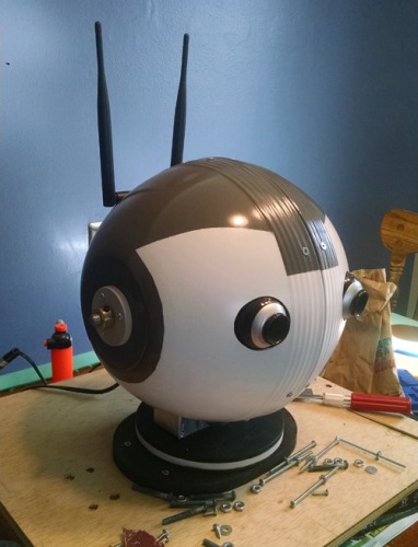
THE HEAD:
The head pans and swivels, and holds two webcams for "eyes" as well as the USB Wireless adapter. You can just make out the WiFi antennas peeking up from behind his head in the primary photo. The head is made out of two plastic (melamine, I think) salad bowls. I am going to let this sequence of photos tell the story.
*** UPDATE ***
I have mounted the rotary encoder for the head "tilt" axis.
As of this writing, I have not completed the interface board with the pull up resisters to send the signals to the controller. Maybe next weekend?
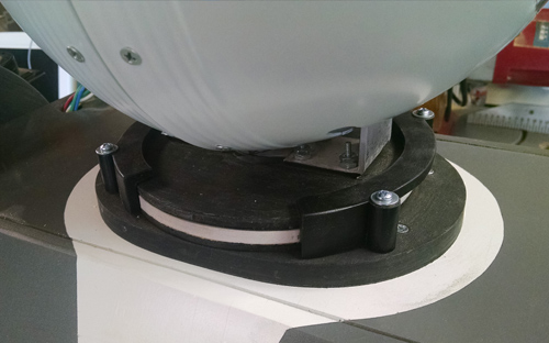
*** HEAD UPDATE ***
When traversing my cracked, broken and heaving driveway, Milo had quite a few jarring shakes. This ended up dislodging his internal "neck" retainer, and let his head bounce around excessively. To correct this, I have fabricated external left and right "retainer brackets" for his "neck". They are pictured below:
(more content goes here)
SOFTWARE:
The software is developed by me, using Microsoft Visual Studio Dot Net. There are a mish-mash of elements, some written in C#, some in VB, others in assembly, all cobbled together under the universal Dot Net runtime. There are two principle components of Milo's Software, The Remote Console that a Human Operator runs and monitors, and the Robot Control Service running on Milo's CPU.
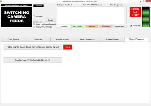
The Remote Console
With very few exceptions, whenever Milo is being operated, for safety reasons, there must be a connection to a Remote Operations Console that can monitor what Milo is doing, and give commands to over-ride Milo's actions, if he is doing something stupid and/or dangerous.
The Remote Console software is something I have written initially for the ScoutBot, and I have just been re-using it and modifying it for use with Milo.
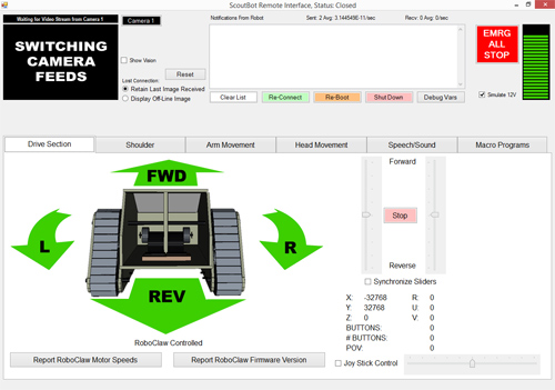
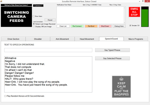
The top panel of the console gives real time feedback from the Robot. I can see a video feed from a selected camera, text notifications from the robot, battery level and such. There is also a software E-Stop.
The lower section of the console is divided into 6 tabbed panels, where each panel focuses on one aspect of operating Milo.
Tab 1 is locomotion, and controls the primary tractor drives.
Tab two is Shoulder rotation and positioning.
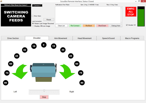
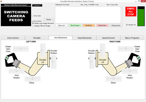
Tab 3 is left and right Arm movement.
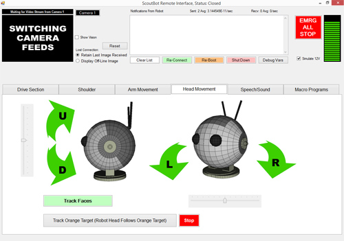
Tab 4 is head movement, and initiating any head autonomous macros, such as tracking nearby faces, or an emergency orange target.
*** UPDATE ***
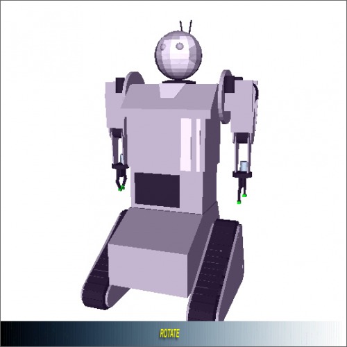
The above 4 panels for making MILO move have basically been replaced by a dynamic 3D Model.
Since I had some time on my hands where I could not work on MILO's mechanical frame, I decided on an update to the control software. I used Wings 3D to contruct simple models of each. Then, using the geometry of those models, I created a "virtual MILO" 3D viewer. Using this viewer, I can now simply "grab" the section of MILO that I want to move, and adjust it visually. Since that is sort of hard to capture, here are a series of screen shots to illustrate the new control method:
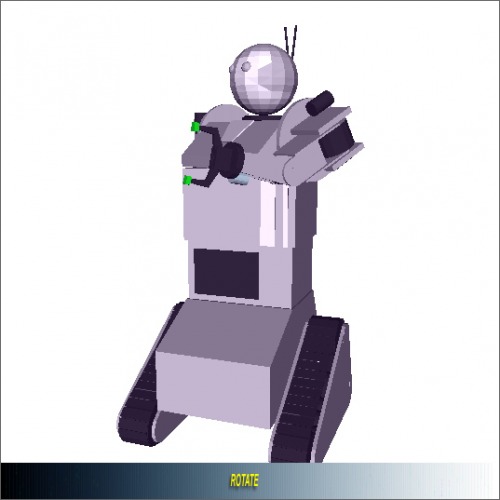
So here I select his SHOULDER to rotate, and a slider control:
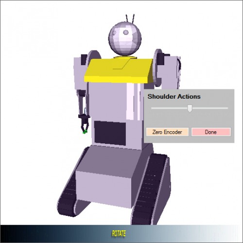
After adjusting the slider, the model (and the Robot) update.
Let's move the arm...
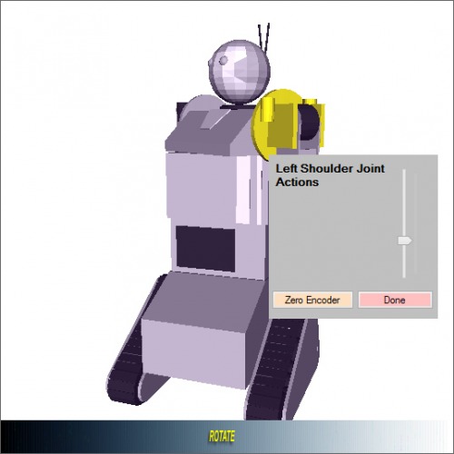
Up it goes...
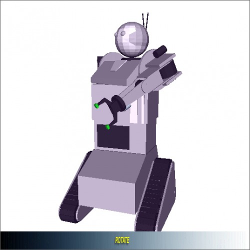
Bend the Elbow...
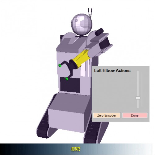
Final Arm and Shoulder position:
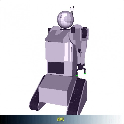
The bottom "slider area" that is labeled "rotate" allows me to spin the model, so I can view it from any angle:
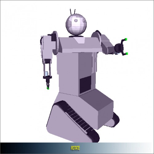
The image above is the same physical position for MILO, just looking at him from a different angle.
Tab 5 is for making Milo speak, either with a canned, "pre packaged" phrase, or anything typed in by hand.
Leftover from ScoutBot is the ability to sound off in Bagpipes.
Tab 6 is the last and most "dangerous" tab. It is the tab for initiating any autonomous operation for Milo.
There are currently two autonomous operations:
- Follow an emergency orange target, where the robot drives towards an orange target, using vision only.
- Read a story book, which is a function for my wife's elementary school class. The kids love it when the robot reads them a story.
(more content goes here)
The On Board Control Service
The software that actually drives Milo is written as a Windows Service, and as such, there are no "screen shots" that can be had, since it does not present any user interface, except for Milo's actions.
I can discuss some of the more interesting parts, and when I have a chance, upload some videos showing Milo doing something driven by the Robot Control Service.
Using the AForge.NET Framework (www.aforgenet.com) I spliced in routines for vision processing. The framework is deep and full featured, and you are really only limited by the computational horsepower you can dedicate to processing images.
Right now, Milo just has a Core 2 Duo processor, which is rather anemic. As such, I have only implemented two vision related tasks with any success. Tracking faces with Milo's head, and tracking an emergency orange target. Milo's CPU can only process about 5-8 images in a second, which in many cases where the robot is moving and bouncing around are not enough. So, currently, vision related tasks work best when Milo is stationary, or rolling on a very smooth surface.
*** UPDATE ***
Santa Claus was good to Milo, and he received a "brain" upgrade. Milo now has a new Gigabyte brand motherboard, with 8 GB of RAM, and an AMD Quad Core processor running at 3.8GHz. Woo, Hoo! He also got two additional 24 volt chassis fans for extra cooling. I just finished installing the fans and replacing the motherboard.
I have also created a simple, interpreted control language called "MILOscript". With it, I can pre-program sequences of operation that the robot will carry out. It allows for actions like driving a certain distance at a certain speed, speaking, or setting the position angles on joints, head or shoulder. Additionally, the script allows for acting on external conditions, such as waiting until a face appears in the field of view.
I am eagerly awaiting some warmer weather here so I can take Milo out of the garage and run him through some paces.
I might be taking him to my wife's school again in the next couple of weeks. I will try to get some good video then for posting.
(more content goes here)
Made to experiment with visual navigation and object manipulation
- Power source: two 12 volt wheelchair batteries
- Sensors / input devices: Motor feedback, Rotary encoders
- Target environment: indoors, Outdoors
This is a companion discussion topic for the original entry at https://community.robotshop.com/robots/show/milo
