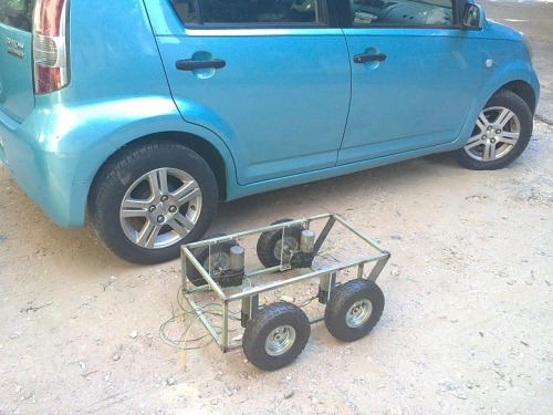
I was going to buy like the ones you posted, but then i saw the big ones that i have now. i think it will be a bit tricky for you to mount wheels directly on the shafts. But you are creative, you will figure this out
Btw, i believe these are window up down motors since they come in lefts and rights. unlike windshield wiper motors.
I believe it tops at about 10-15 A in normal use and jumps to 40-50 A when stalled. I have designed and built my own custom hybrid controllers for these motors that should be able to hold peaks of up to 70 amps and more .
each motor has its own motor controller, besides that each of these motors has a built in switch that gets pressed once per rotation, so i can roughly estimate the RPM of each motor.
I’m not sure who was doing the work on the lathe, but some of those pictures are very scary indeed.
I in absolutely no way intend to cause offense, but the image with the parting off tool, and the one below it with the one with the vernieer gauge might not be best things to show on an educational forum - both show very dangerous ways of working, and could cause people to loose fingers or get badly injured.
The robot itself looks like it’s going to be great.Please keep the updates coming.
As I have two years of school with lathe and other machines I do agree that this is some scary pictures.
That said I do envy anyone having this type of low cost fabrication in their neighborhood. To get anything like this done in Norway it would probably cost you $100 just to look at your drawings.
The man has some 20 years of experience on that particular machine, i was close only during the taking of these pictures.
I quite understand your concerns and i chatted with the man about it and he told me about an accident that happened on this machine with a man’s scarf getting caught in the spindle resulting in catapulting the man into the wall causing severe injury.
I got 4 shafts machined and welded to the motor shafts all for 40 US$ And the process nearly needed all the expertise this machine does ! also done in under 2 hours same day i spoke to him.
I don't know if this picture is clear but this is how I mount those motors and the image below are the mount plates. They are different because both motor are same side so these plate have to be made differently to hold motors in same position.
BTW, I am not too sure but if I were you I would use stronger wire like 10~12AWG at least and have 30A or 50A fuse in each motors, depands on how much AMP your motor may consumed. Again, not 100% sure if I am correct but that's how I use on my tank.
That sounds good. Yeah, those wiper motors usually 50A when stalled. If you could handle up to 70A that’s good enough. Make sure you use thick wires or it might get hot easily if it go over 30A.
Ok cool stuff the intern switch is a useful stuff.
I was thinking to use windscreen wiper motors transforming them on electric linear actuator (indeed i made this type of actuator with servomotor, for a biped i build just now), but the type of motors you use could also be a good solution.