This represents my first attempt at any robot. Not the happy ending that I expected. Even after two tries still nothing. I followed the tutorial found here :--> http://www.geocities.com/SouthBeach/6897/photovore.html . I checked everything i could i even used a smaller motor salavaged from a hexbug i paid $6 for. Anyways this has not detered me at all. Back to the drawing board. Oh by the way, its always a good idea to use a breadboard first , no matter how confident you are that you've got it all correct.
For the brain I bought the following from Solarobitics (i doubled the qty of each item required from teh tutorial) :-
2N3906
2N3904 (corrected thanks Krumlink)
0.22uf Monolithic Capacitor x2
Pager Motor Style 2
1381 J Trigger - 2.7 to 2.9V
24x33mm Polycrystalline Solar Cell (rated at 4.5v / 18ma)
100K 20 Turn Trimpot
Wide Field of View Infrared Photodiode Detector
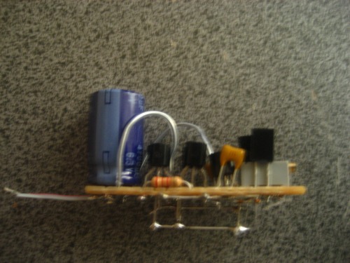
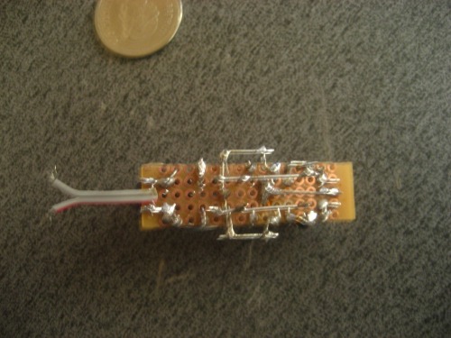
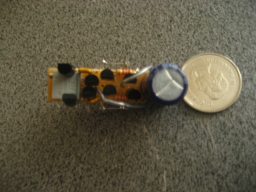
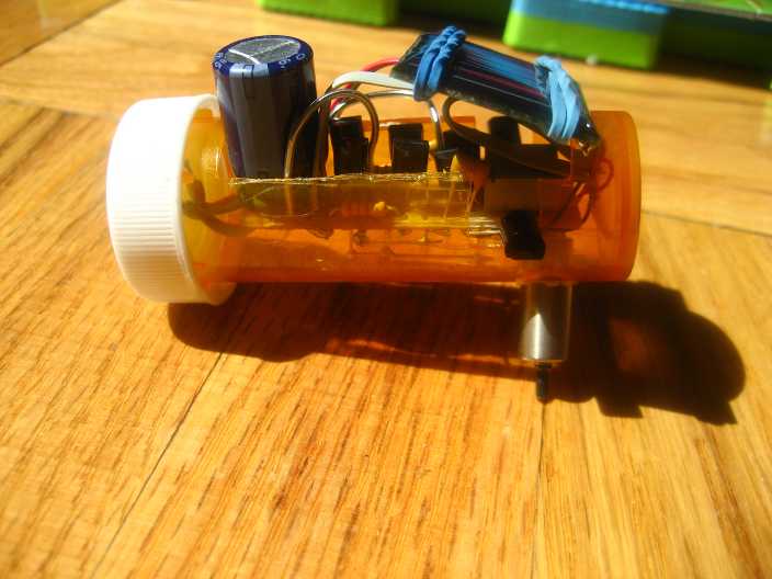
I'm pretty convince I messed up the order or at least mis read the instructions. Thats the only explaination why two separate builds still nothing. I'm saving up some more money to get myself a Breadboard. Will be debugging both photovorescomponent by component. My solar cell and pager motors were setup to be detachable and i didn't include them in my pics. When I get home later I'l show the full assembly. Oh yeah I cheated a bit and used a prototyping boad i bougth at TheSource. See more pictures below :
May 31, 2009
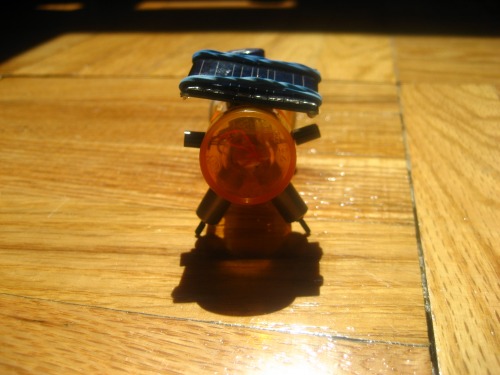
After rechecking and taking apart my second of the two photovores I got two brilliant days of awesome sunlight and to my amazement my photovore sprang to life. It turns out that even though i figured the lights at home should be sufficient to power the solar cell it wasn't at least not for my photovores. The same cell powered my single motor symet but not the photovore. Thanks again to all the commenters. I'm off again to plan my next project.
P.S. Will be posting a video of my final bug shortly
Make sure your capacitor charges up past 2.9V. If you’re testing under a lamp sometimes your solar cell won’t give you enough power. Also, it’s hard to tell in your pictures by looking at the bottom, but the wiring diagram you are referencing has all of the transistors facing each other and you have all of yours going the same direction. I’d double check to make sur you’ve properly flipped all of your wiring.
Folks thanks again for all the comments. I desoldered the second build and used teh components to make a SYMET. Within 1hr and 30min I had a fully functioning SYMET. Solar engine twitching and all. I have now narrowed my problems with teh first bot to somewhere between the trimpot and the photdiodes. Will update as soon as I figure out which one was it.
solar beam bots go in bursts - they slowly charge up the capacitor from the solar panel, and monitor the charge level. When the charge level exceeds some value, the capacitor drains into the motor. In direct sunlight this process can be pretty smooth and contiguous, but it otherwise moves in bursts. Removing the capacitor would make the circuit completely nonfunctional -unless a charged battery were hooked up instead, but that would defeat the purpose!