Measure output voltage PWM motor driver, RMS and average voltage, dc motor parameters

Hi everyone. I ´ve bought this dual dc motor driver in RobotShop https://www.robotshop.com/es/es/cytron-conductor-motor-dc-doble-canal-10a-5-30v.html to control 2 dc motors with PWM and Arduino. I´d like to know what output voltage of the motor driver should I see reaching the motors. I´ve some doubts about some dc motor parameters too.

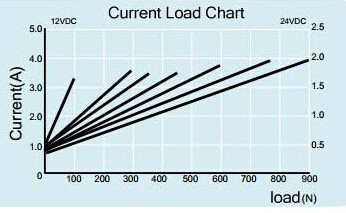
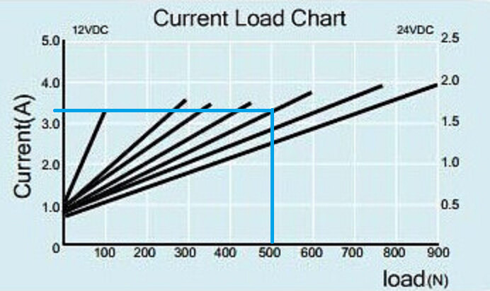
For example, I want to control a 12V dc motor which has a current of 3A with a load of 500N, if I introduce a duty cycle of 50%, what output voltage of motor driver should I measure? I´m very confused with this topic because I´ve seen a lot of different ways of calculating this.

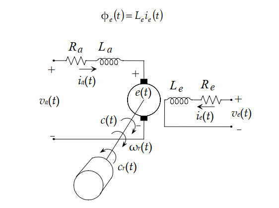
First of all, I´d like to check the dc motor parameters:
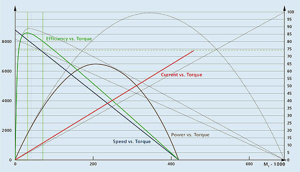
Power = Voltage * current = 12V*3A = 36W
Resistance = Voltage/Current = 12V/3A=4ohm

Is this resistance constant? How can I measure this motor resistance with a multimeter? Do I need the motor to be working in a specific way to measure this resistance correctly with the multimeter?

Once I have the motor parameters, I´m going to explain my doubts. For example, with a duty cycle of 50%, I´d have the following calculations with the average voltage:

Vave = 0.512V=6V
Iave = Vave/R=6V/4ohm=1.5A
P=6V
1.5A=9W

Why do I have a power of 9W? That is the 25% of the total power, shouldn´t I have the 50% of the power, I mean, 18W?

If I use the RMS voltage, I´ve the following calculations:
Vrms=square root(duty cycle/100)*V=square root(0.5)12V=8.48V
Irms=Vrms/R=8.48V/4ohm=2.12A
P=8.48V
2.12A=18W

If I use the RMS values, I´m obtaining the correct power I think, but my question is, why is there that difference? What values do I have to use? Will my dc motor have a power of 18W(50%) or 9W(25%) with a duty cycle of 50%? Will my dc motor receive a voltage of 8.48V and a current of 2.12A or a voltage of 6v and a current of 1.5A (or 3A to obtain 18W)?

I´m not sure of the calculations, so the first question is if they are correct.
And for finishing, will I need a trueRMS multimeter to measure the correct values?

Forums/Blogs list where I´ve read different things:

1.Here it´s said that with a duty cycle of 50%, you obtain a power of 25%:
PWM not causing motor to turn until 50%

2.In this forum, the poster has a doubt similar to mine (I think), and people say that he obtains a wrong value (25% of the voltage with a duty cycle of 50%) because of he is measuaring with a normal multimeter, and they say that you can obtain the correct value (50% of the voltage with a 50% of duty cycle) with a TRMS multimeter, hence, you obtain the correct power:

3.Here it´s said that you can calculate the RMS voltage of a PWM with a constant = 0.7:

4.Here it´s said several things. Firts, they say that RMS voltage and average voltage are the same. Then, they say that with Vrms, you obtain the 50% of the power with a 50% duty cycle and the 25% of the power with a 50% duty cycle if you use the average voltage for your calculations. Later they said that if you double the voltage, you will quadruple the power:

5.Here it´s said that if you use DC with no ripple, Iavg= Irms and Vavg=Vrms:

  1. Here there is another discussion about what values you have to use for the calculations (rms or average):
    https://www.avrfreaks.net/forum/rms-current-measurement-square-signal

Thank you very much,
Alberto.

1 Like

That’s a great pick! That motor controller is by far one of my favourites!

Do you mean with a multimeter (open vs under load)? Or are you unsure with connection points to attach to your DC motor?

My assumptions here:

  • The DC motor is rated for 12 V DC.
  • You are providing the motor controller with 12 V DC from as power source that can provide enough currents. Maybe rater for 5+ A? As you get closer to the maximum rating of a power source they typically start dropping in voltage (unless they are of very high quality)
  • The motor has a stall current of 3 A when loaded with 500 N of torque (or ~0.5 kg)

Assumption: duty cycle of 50% is in relation to the PWM driving the motor controller signal.
Following the assumptions above, you should measure ~6 V DC.

Your main issue here is that you are trying to treat the DC motor as a DC circuit in a steady state, which it is not.
The motor itself is effectively a large inductor and the inner coil’s resistance is only one parameter affecting how it works.

Also, while typically you get a inverse relationship between resistance and current vs a fixed voltage, DC motors (again, because they are an inductor with magnets) don’t act like static components. As you drop the voltage the coils are less energized and produce less torque (and also use less current). Also, a DC motor running at a lower voltage than the one it is rate for makes it less efficient, too (i.e.: more input power needed for less power output produced).

Said differently: the typical way of controlling a DC motor’s speed is to vary its average voltage (i.e.: lower than the rated one). This effectively makes it also produce less torque than the maximum rating provided (which is spec’d at rated) voltage at a lower efficiency.

I think the calculations in this case won’t matter much. What I recommend you do instead if you want to obtain better data for your DC motor is this:

  1. Place a multimeter in series with the power source and motor controller (i.e.: between them). Set it to measure current.
  2. Place a multimeter in parallel with the DC motor. Set it to measure voltage.
  3. Do the following tests with a 12 V DC power source with enough current capabilities (I’d say at least rated for 5A, maybe more):
    a) Set the motor with no load (free rotation). Set PWM setting to 100% in one direction. After voltage & current readings are stable, note them down.
    b) Set the motor with no load. Set PWM setting to 50% in the same direction. Get voltage & current.
    c) Set the motor with no load. Set PWM setting to 25% in the same direction (or whatever low voltage to which it stills turns enough. If it stops turning that’s too low TURN OFF POWER NOW or you may damage your motor). Again, get voltage & current.
    d) This is the tough one. Set the motor with a massive load (i.e.: with which it will not turn at all). Set PWM setting to 100% in the same direction. Get voltage & current quickly!. You do not want your motor in the stall condition for very long (a few seconds at most or it’ll heat up and die quick). Maybe take a picture of the stable values and cut off power super quick!

And now you have some data on your DC motor and how it reacts to voltage and loads (no load vs stalled). You can then go ahead and get started placing that data in a nice characteristic curves of your DC motor, kinda like this one:
image

This is the kind of graph you want to let you know how a motor will react in different situations! Though this one is not the greatest since the units are missing (which happens more than you think… :stuck_out_tongue: a great sin in science! That and not labelling your tables/graphs!).

Here are some links that may help you move forward with this task of understanding your DC motor:

Sincerely,

2 Likes

Thank you very very much. As always, your answers are awesome.

I´m using a 12V DC power supply which can supply big currents but when I finish the prototype, I´ll change it by a battery, so this is an importan point too. I mean, this is the chart of my DC motor, where you can see the current vs the load:
image
The load that has to be moved by the motor during the process is of 500N, so I guess that the motor will need a current of 3A during the process, right? I mean, when you say a stall current of 3A when loaded with 500N, stall current is the current when the motor is blocked isn´t it? I don´t understand that very well.

I get it. I understand my mistake. So we can say that the lower PWM, the less current it consumes, right? And when you say with a lower efficiency, do you mean that with a duty cycle of 50% for example, won´t I obtain a power of 50%? If yes, how much less power will I get?

Great! It seems like a very good way to get the data. Should I do the same experiments with the load of 500N?
I´ve read too that to obtain good results measuring PWM signals, you need to measure with a TRMS multimeter, since normal multimeters can´t measure square waves, only sine waves, that´s right?

Thank you very much for the links too! :grinning:

1 Like

From that chart, it seems like a load of 500 N would use about 3.3-3.4 A @ 12 V DC.
image

Stall current is tied to the stall torque, i.e.: the current the DC motor consumes when trying to move (at full power) but unable to do so. Typically that spec is given for the rated voltage (in your case, either 12 or 24 V DC).

Typically the two most important points are the continuous current consumed & RPM of the output shaft without load (i.e.: zero additional torque required on top of the internals of the motor) and the current consumed when stalled (RPM=0), both measured at rated voltage.

These allow you to get a good idea of the motor’s performance curves since they are the end points of how it will perform. As a side note about power, check this. Neat for quick calculations! :slight_smile:

You’ll quickly notice that a value in N by itself is not enough to know much. I’ll assume the value described is at the shaft (i.e.: 500 N @ 0 distance from the center of the output shaft). Hopefully I am right! :smiley:

The basic relationship says that if you output the same amount of power (the work done by the actuator) and change the voltage, the current changes in a inversely proportional way. That being said, DC motors are a bit more complex than that and a lower voltage DC motor also has a lower maximum torque, therefore needing also less total current (but more than before for the same amount of torque, since the voltage is also lower).

I guess it is easier to say: this is not a linear relationship (but in a lot of cases can be approximated as such when the data is well known). Just keep in mind that the current consumed is tied to the torque produced.

All actuators have a “sweet spot” where they produce power the most efficiently i.e.: the loses are the lowest between input power and output power. In the graph above (my last post) you’ll notice that motor’s performance curves indicate an efficiency of just above 85% at a torque of around 45-55 (whatever units of torque they used). If you use it with a load creating a lower or higher torque requirement then the efficiency will be lower, i.e.: the total produced power will be lower vs the power consumed. This is ultimately a 0% efficiency when stalled where maximum current (@ rated voltage is produced) but no work is created (stalled @ maximum torque).

That’s the wrong question.
At 50% duty cycle you’ll provide the DC motor with 50% of the voltage your power source is producing.
This will lower the speed of the DC motor (not exactly by 50%, depends on load too!) but also the maximum torque (which affects the power you can produce). Of course, this also changes/distort the efficiency curve (if you know it for the rated voltage).

Complicated question without the full specs of the DC motor. It is far easier to answer empirically! i.e.: test it out!
You can go from stall at 12 V DC to stall at 6 V DC, etc. and see how much load you require to stall the motor. You can also test this in two different ways: when starting motion from fully stopped (and no motion happens/stalled) and when already moving (increasing torque until stall). Of course, those tests can be risky if you are not careful as they can be destructive (to the motor first, but also indirectly to motor controllers and power sources). Make sure to let all parts cool down sufficiently between runs!

As far as I know, TRMS only really applies when measuring AC signals. See this for some details. Unless you are doing something weird, your PWM signals are all rail-to-rail positive DC voltages (no alternative current). Just stick to measuring in one direction of motion and I don’t expect much issues doing basic measurements.

On top of the articles linked above, maybe have a look at this question & its answers.

1 Like

Great! I get it. just one more question about the current, I´ve read that the starting current can be 5-8 times the nominal current, for example, that means that if my actuator has to start with the load of 500N (hence, nominal current equal to 3-3.3A), could the starting current be 15-24A?
I know that I´d be able to obtain this with a quick test, but my multimeter only can measure currents until 10A, and I wouldn´t like to have a grilled multimeter :sweat_smile:

I get it, so if a code a progressive starting with PWM, demading it less torque since the first moment, with the goal of reducing the starting current, that should work, right? Since lower voltage is equal to lower maximum torque and that is equal to less current

Okay, so I can assume that the only assumption you can do is that you´ll obtain half of the voltage with that duty cycle, and that the power will be lower but not in a linear relationship.

Great! Another way would be by measuring the current at that momento, right? So, in that case, do I have to use the (stall) current just in the moment that the motor stall at 12V and 6v, and then multiply that stall current by the voltage? Or should I use the current just before stalling? Since I understand that if I use the stall current, I´ll obtain a wrong power, because that current will be much higher and the motor would be stalled

Perfect! I´ll use my normal multimeter then.

Thank you very much! :grinning:

Yes, exactly! Batteries have (usually) less trouble with this and “wall warts” (small AC-DC converters typically in a black plastic box). Better quality supplies may do well, too, like those larger laptop-sized ones or those meant for lab equipment.

Oh, and also it may not be fast enough to measure it, either! :smiley:

Just make sure it is not so low as to stall it! A smooth ramp-up is key in most electric systems with significant loads (electrical or physical!).

Yes. :slight_smile: Unless you model your DC motor’s characteristics fully (see links above), you won’t really know all the details.

I think this link might be interesting on this subject. Before you read it though, keep in mind the first paragraph has some mistakes in it and the second one corrects those with good details! :slight_smile:

And, if you feel like it, the full model for a typical DC motor with transients:
image
As you may notice, time (t) is a big factor everywhere since all those values (well, except resistance :D) change in response to each other.

But definitely if you retain anything from the post above, please retain this: use a lower voltage than the rated (or maximum) voltage for your DC motor for testing stall torque and extrapolate from other characteristics of it the possible value at the rated voltage. This will be accurate enough for your needs and far less likely to cause damage.

The stall current + rated voltage effectively gives you the power the motor can put out at its best effort (since it is not moving). It might be good to know that for an actuator, the power is a combination of torque and speed. Therefore, since measuring current is much easier than measuring speed it is a simple way to get total power with the motor speed not contributing at all to the calculation (i.e.: stalled).

:+1:

Hehe, no problem. You are forcing me to review stuff I haven’t used in a while, too… I mostly do wireless stuff lately (Zigbee, OpenThread, WiFi, etc.).

Thanks a lot! I think I am ready to start my experiments and know the causes (or consequences) of the things that I am going to face.

Very interesting the part of how to measure the stall current by decreasing the voltage, I will definitely do it that way

Thank you very much again for helping me, I really appreciate it, I don’t know how I will be able to return this help to you one day. For now, thanks to people like you, I will help all the people who need my help on the internet.

1 Like

:+1:

Yeah, it is a good trick. For most use cases it is enough precision and much less risky! :slight_smile:

:+1:

Exactly that! :slight_smile: Help others, share knowledge and experiences! Make all of it better! :smiley:
Oh, and of course, make a page for your project so others can follow and learn from your process!