

![]()
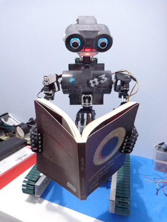
MDi #3 means Mech-Dickel interactive number 3. Well, it's not going to be something so interactive like Jarvis, but I hope I'll have much fun with it.
On the process of planning and building this project certainly I was very influenced by Johnny 5 and Wall-E. Actually at this time I can't imagine a better look for a friendly interactive robot.
This robot is going to be able to run around autonomously (with some sensors) and also will have a remote controlled method.
![]()
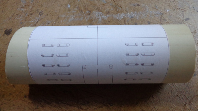
At this moment the mechanical part is almost done. The most of the parts are made at home by myself using polystyrene, and you can see how I made my custom parts on this walkthrough I did some time ago, that uses the toner transfer method.
Toner transfer method X Water based glue method
The toner transfer method is used commonly to make quickly PCBs, and I've adapted the method to use with polystyrene. Since my first robotic project with polystyrene I'm using this method, that provides us a good precision to make the cuts. I utilize this method to make small pieces, where the hot iron can reach the whole piece. For bigger pieces (for example, the chassis part), that don't need much precision and don't have much tiny details, I just glue the template over the polystyrene sheet and then realize the cuts and holes. Using the toner transfer method in a bigger piece can result in a bad looking, because the hot iron can't cover the whole piece, leaving a hot section and other cold, and the piece will end up getting wavy.
So, toner transfer method is good for small pieces with many details and water based glue method is better for huge pieces with less details.
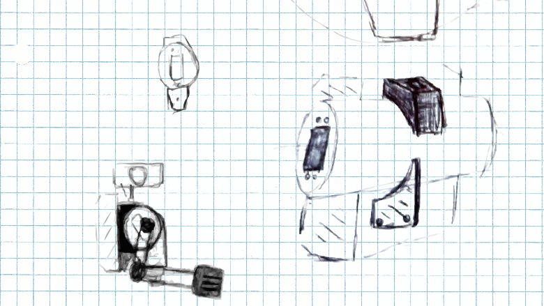
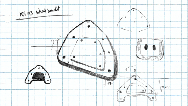
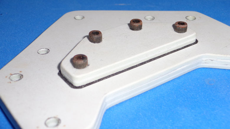
The conception of the parts
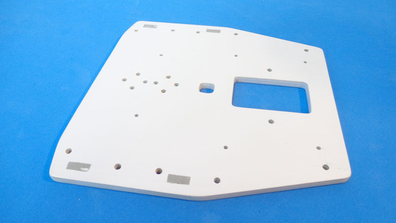
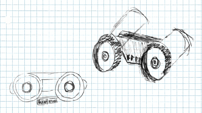
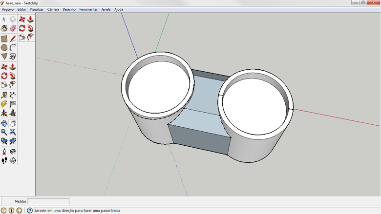
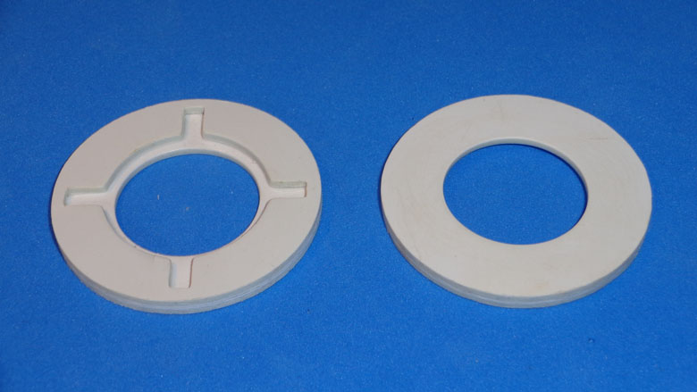
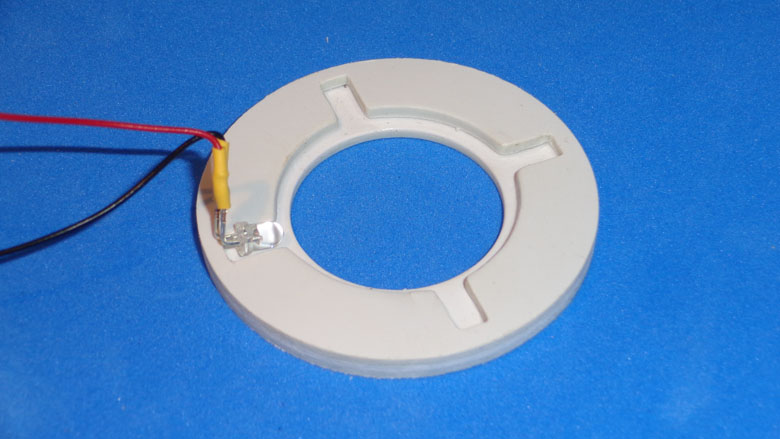
Commonly I start up with a brainstorming and make some sketches till I get something satisfactory. Sometimes the SketchUp helps me to take a good perception of complex parts. Below you see on the pictures some parts from design to the manufacturing.
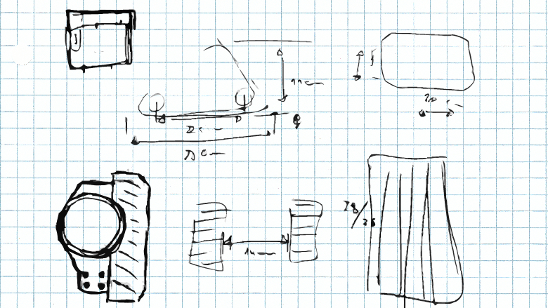
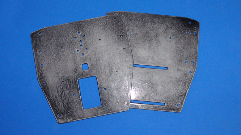
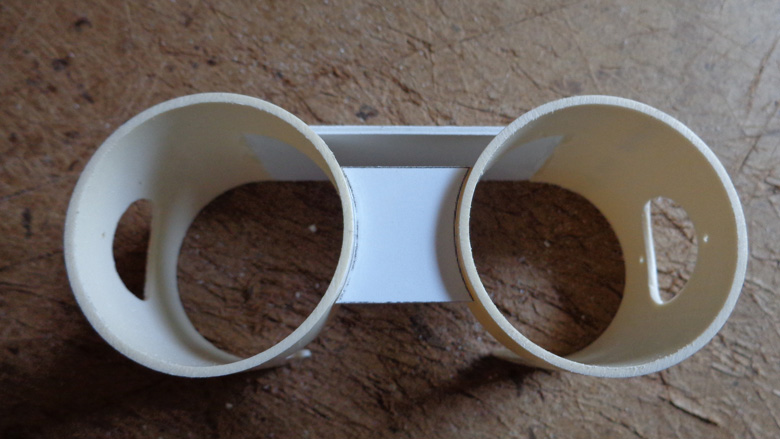
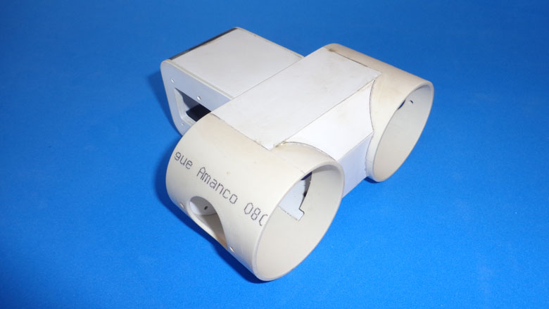
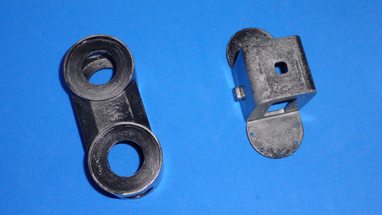
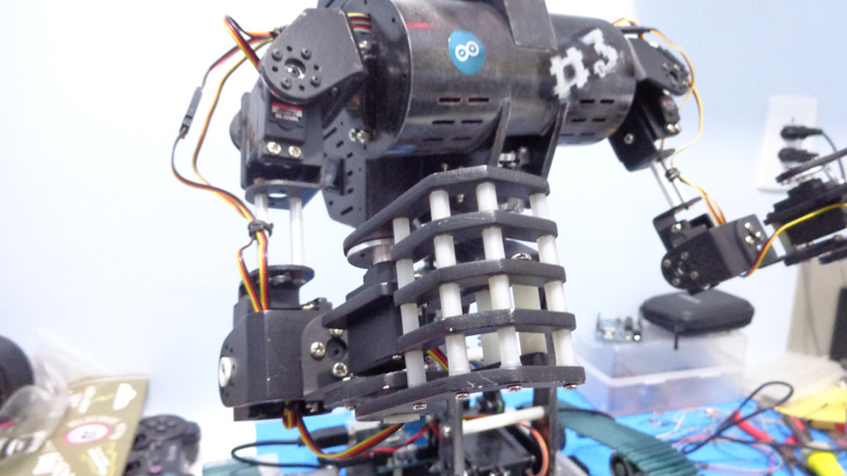
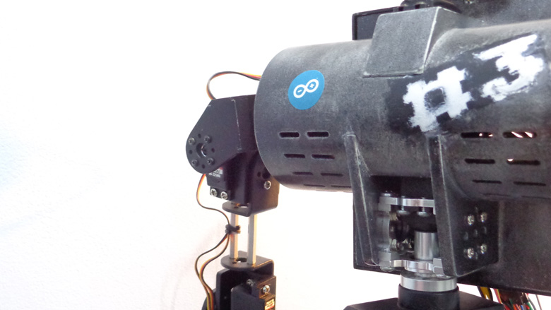
Besides polystyrene, the main part of the torso is made out of a 75mm PVC pipe.
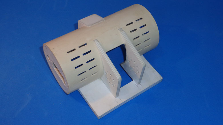
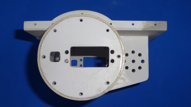
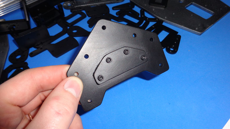
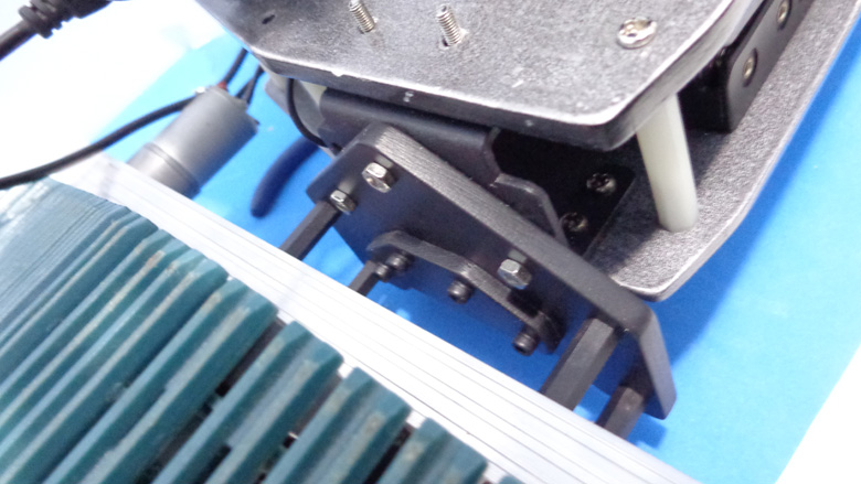
This part is used to attach the chassis to the aluminum bracket of the tank treads.
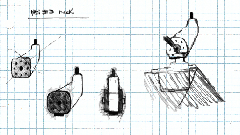
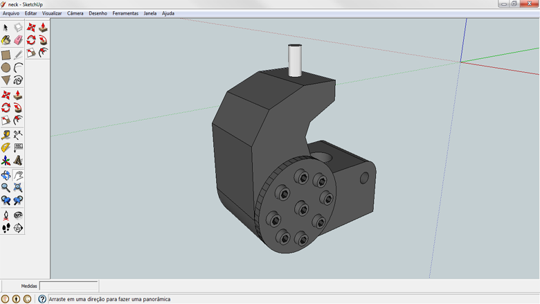
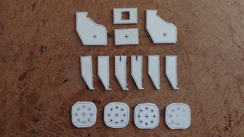
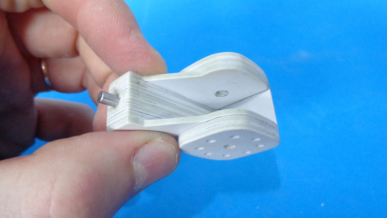
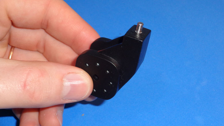
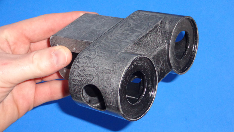
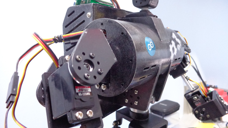
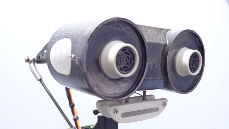
Maybe the part that I've dedicated more time to design, the head have many friendly appeal features, and I think in an interactive robot it couldn't be different. To get this look I changed the design a few times, and ended up influenced by the Lego EV3 ultrasonic sensor.
On the inside of the eye there are grooves for 4 X 3mm leds.
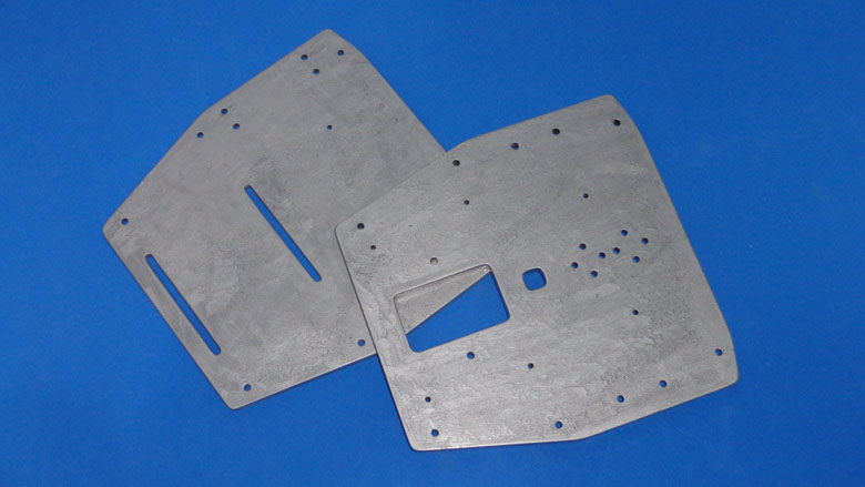
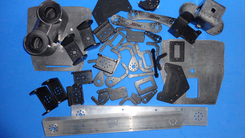
Here you see all the homemade parts of the project done, except for the torso and the electronics bag, that at moment of the picture was taken was waiting for the paint to dry. Here you see about five months of hand work. :)
All the parts are made out polystyrene sheets and PVC pipes, except for the two at the bottom of the picture (the tank treads bracket), made out of an aluminum channel.
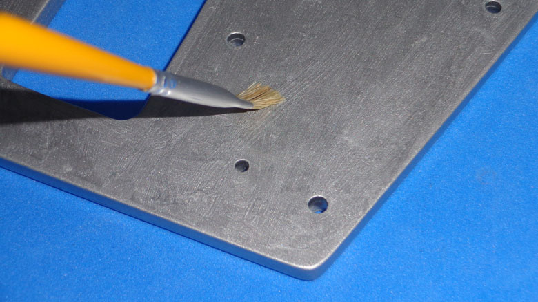
The small parts was painted with matte black, and the bigger/main parts (chassis, electronics bag, torso and his interconnector bracket and the head) was painted with a technique highly inspired by what lumi did on the Steampunk Goggles.
For the main parts, first I've painted with silver spray painting and then passed with the brush to make some roughness. After the paint was dry, painting it again a bit with matte black. After, scuffed it a bit. I finished with clear lacquer.
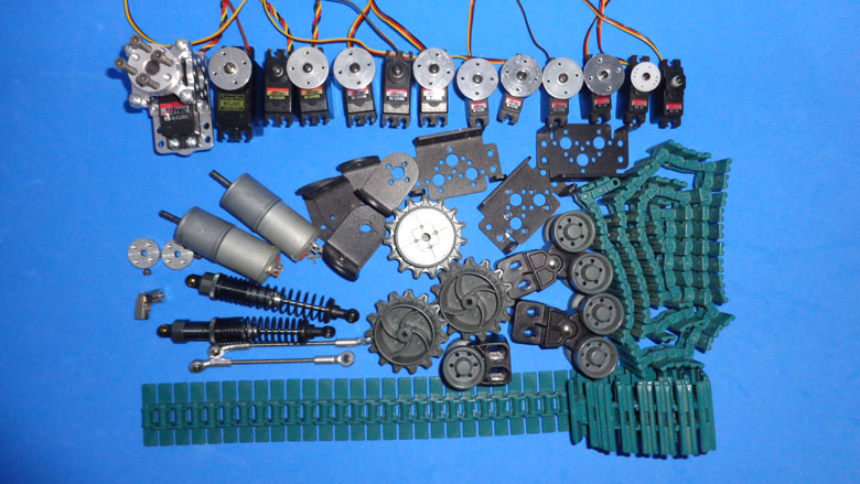
List of mechanical items:
- 1 X Vex tank tread kit;
- 2 X RC car shock absorber;
- 1 X shaft coupling motor connector;
- 4 X curved steering linkage head;
- 6 X L aluminum bracket;
- 3 X aluminum servo bracket;
- 2 X aluminum motor hub;
- 2 X DC 5V motor with gearbox;
- 1 X ServoCity load bearing servo block (Hitec);
- 1 X Tower Pro MG995 servo;
- 1 X Hitec HS-645MG servo;
- 2 X Hitec HS-5245MG servo;
- 3 X Hitec HS-225MG servo;
- 3 X Hitec HS-82MG servo;
- 3 X Hitec HS-81 servo;
- 9 X Lynxmotion (Hitec) spline metal servo horn;
- Ultrasonic sensor mounting bracket;
- Many many screws, nuts, washers.
MDi #3 templates
If someone want to reproduce this project, or even just some parts, here (https://drive.google.com/folderview?id=0B2gOXfxaf2xjdld0SWV3VDd6M2c&usp=drive_web) is a folder created on Google Drive where I'm sharing the templates for many parts.
To print it in real size I just paste the image file in a text editor and adjust the document to be borderless, than print it in A4 paper sheet (210 X 297 mm).
![]()
The brain of MDi #3 is an Arduino Mega2560, that receives inputs from all the sensors and the remote control and also controls the servos and the DC motors (with a L298N).
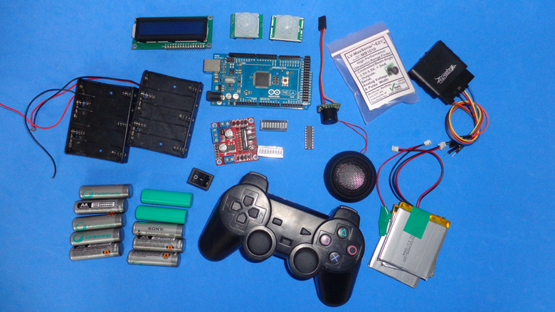
List of electronic items:
- 1 X Arduino Mega2560;
- 1 X L298N breakout;
- 1 X PlayStation 2 wirelles controller and receiver;
- 1 X small speaker;
- 2 X Ultrasonic Range Finder Maxbotix LV-EZ01;
- 1 X HC-SR04 ultrasonic sensor;
- 2 X PIR sensor;
- 2 X 5XAA battery holder;
- 1 X LCD 16X2 display;
- 1 X power switch;
- 2 X 10 segment LED bargraph;
- 1 X LM3914 IC;
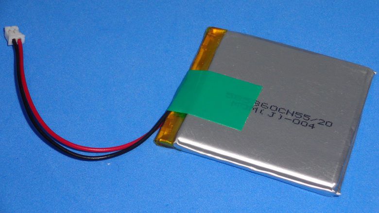
- 3 X 2000 mAh LiPo battery;
- 10 X AA NiHM 2500 mAh battery;
- Some LEDs and resistors;
- Many many jumper wires and servo extension cables.
PlayStation 2 controller
Since my first robotic creation I'm using this joystick to control my projects. It's a cheap controller, easy to interface and have much info about Arduino + PlayStation 2 controller on the web. I'm using the library for Arduino made by Bill Porter. On his page have much info and also the library to download and the wiring scheme.
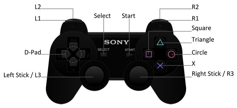
Combos of MDi #3 remote controlled routine:
-
 /
/  /
/  /
/  : controls the locomotion (DC motors);
 -
 +
+  /
/  : head pan;
 -
+
 /
/  : head tilt;
 -
 + / : rotation of the torso and at the same time head pan;
 -
 +
+  /
/  : right shoulder up and down movement;
 -
+
 /
/  : right shoulder in and out movement;
 -
 + / : right elbow up and down movement;
 -
+ / : right hand (open and close);
-
 + / : left shoulder up and down movement;
 -
+ / : left shoulder in and out movement;
-
 + / : left elbow up and down movement;
 -
+ / : left hand (open and close).
LCD 16x2 display
The first idea for this device was to use it as a data logging display, like the range measurements from ultrasonic sensors and the human motion detection from the PIR sensors. Maybe this features will be used later.
But the main reason to use the display now is to be a menu.
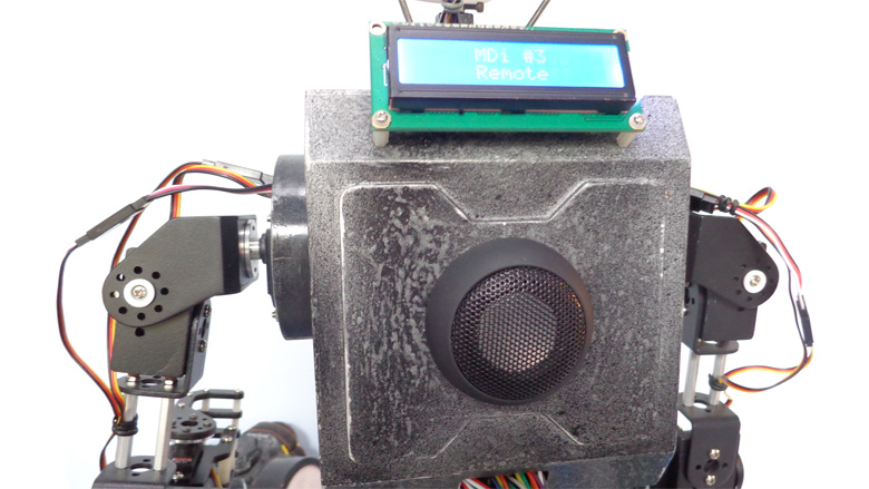
This robot will have three modes/routines: Autonomous, Remote controlled and Stand by.
The Autonomous mode will be a simple obstacle avoidance routine with inputs from the ultrasonics sensors (LV-EZ01 and HC-SR04), and maybe make some beeps
The Remote controlled mode... well... the name speaks for itself! All the control in my hands!
The Stand by mode will be an idle routine. The robot will be stationary, just moving his head and hands, waiting for some human motion detection from the PIR sensors, then MDi #3 will make some interactive movements and beeps.
On the display will be shown the current selected mode and will be possible to change the mode.
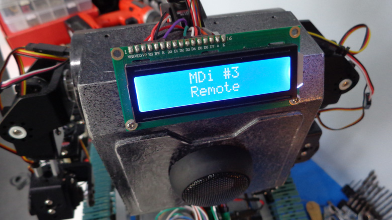
The below picture shows the first screen when the robot turns on.
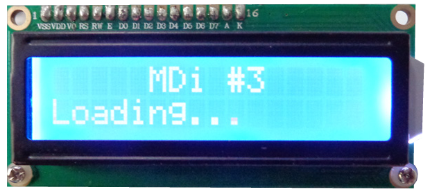
After [Loading...] screen comes the main menu ( [Select:] ), with the three options: [Autonomo] (Autonomous), [Remote] (Remote controlled) and [Stand by].
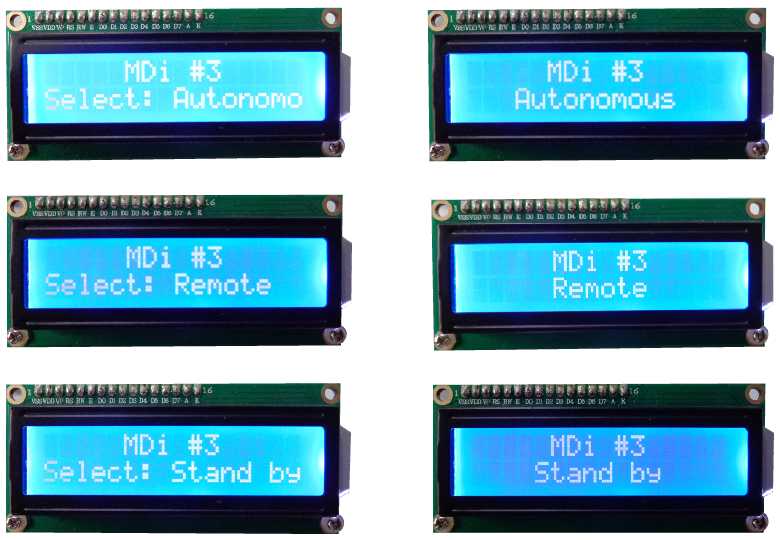
"UP" and "DOWN" buttons from the PS2 remote controller are used to choose between the modes, then "START" button must be pressed to go to the selected option. To return to the main menu "SELECT" button must be pressed anytime.
The screens bellow shows on the left column the modes on the main menu and on the right column the choosed mode (after "START" button was pressed).
Power supplies
The servos are powered with two sets of 5XAA NiHM cells (i.e., each set 6V), connected in parallel, which provides 5000 mAh. The DC motors are powered with three LiPo batteries connected in series (i.e., 11.1V). Auchhh!... the DC motors are 5V! Well, well... I know it's not recommended, but as the DC motors are a bit weak with only 5V, I'll be doing this till I get stronger motors (or till I burn these out!). This overpowering increased considerably the torque and speed of my motors. If someone of you guys will try something like this I do recommend to read first this excellent article about overpowering DC motors.
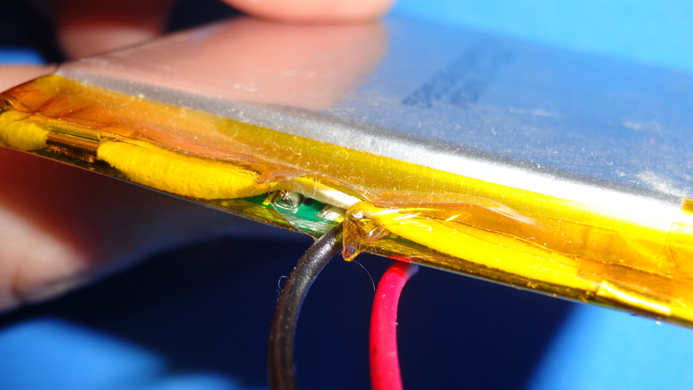
Broken wire.
I love to use this LiPo batteries from SparkFun. I use them in all of my projects. But, as suggested by SparkFun, wrap it a bit immobilizing the wires with electrical tape, as soon as you can! If not, it will end up like the above picture.
Something not so bad... easy to fix... But it can happen many times and thus is prevented.
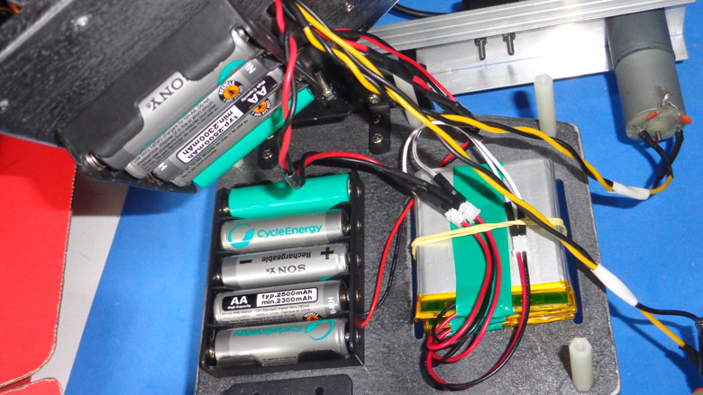
All the batteries attached between the two layers of the chassis.
DC motors + servo motors + PS2 remote controller = what a noise!
With all the parts assembled and the connections done, it's time to have some fun! Oh no... the servos went crazy! When I send a command from the PlayStation 2 controller to turn the DC motors the servos starts jittering. Not just a bit of jittering, really a freaking jittery! This problem was solved with some tips found on this page about RFI (Radio Frequency Interference).
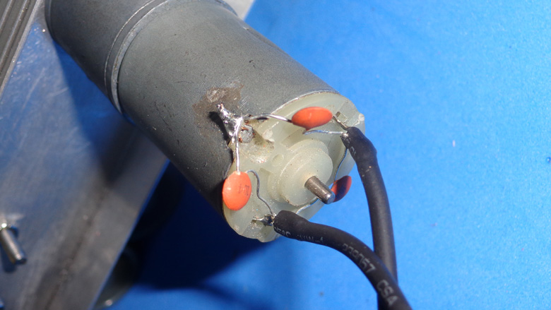
With just three 0.1uF ceramic capacitors for each motor the interference and noise goes away!
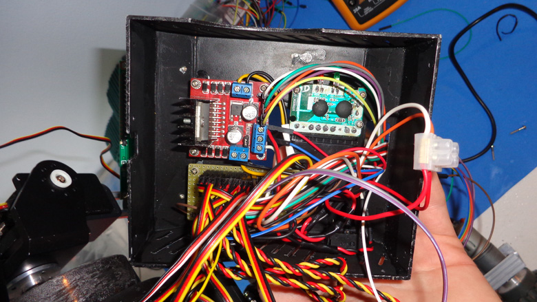
Inside of the electronics bag are mounted the L298N breakout, the receiver of the wireless controller and a small homemade PCB for the power supply of the servos.
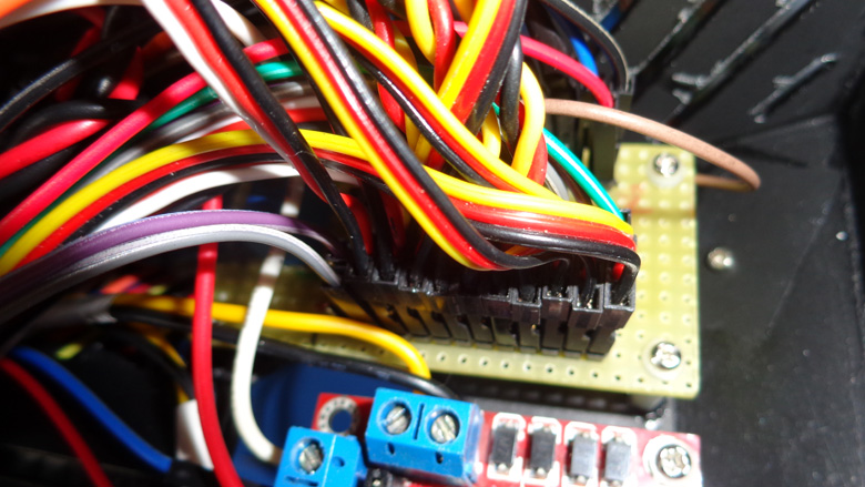
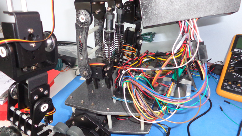
The Arduino board is mounted on the chassis. What a mess of wires! But it's working, with no short circuit! :)
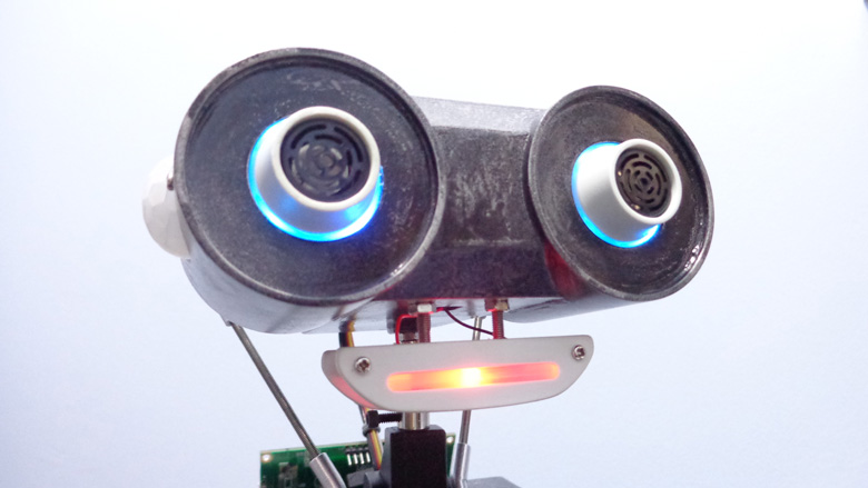
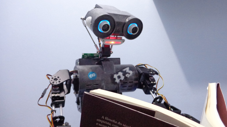
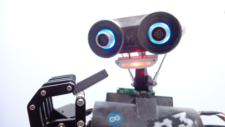
Head features
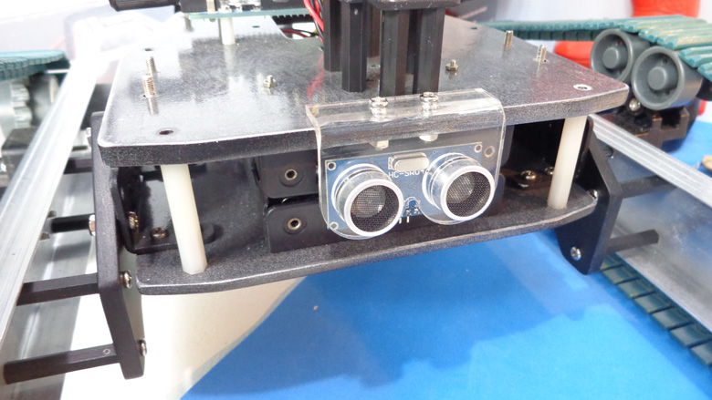
The head have some friendly features, like his LED eyes with ultrasonic sensors, PIR "ears" and have also a LED mouth.
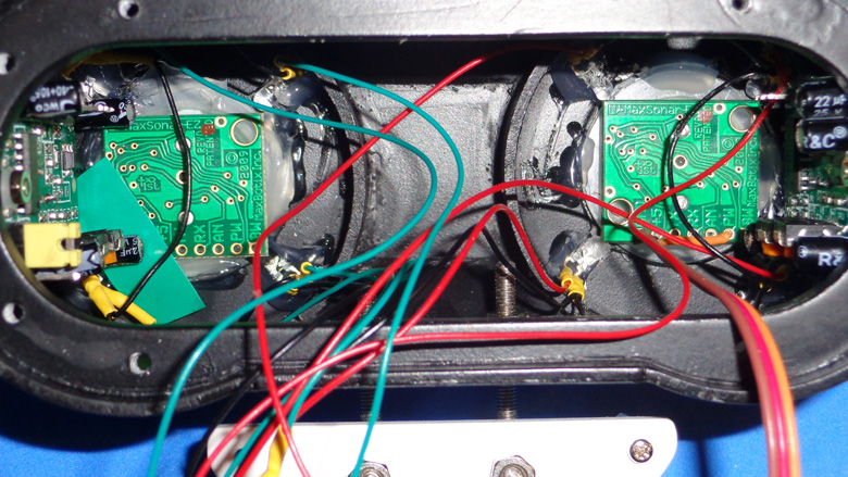
Inside the head: PIR sensors, ultrasonic sensors and the LEDs of the eyes.
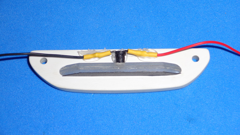
The mouth is made out with three layers of clear acrylic stripes.
![]()
Updates:
@ June 7, 2014: added info about the mechanical part; most of the parts are painted.
@ June 15, 2014: new video added (remote controlled running).
@ June 17, 2014: added info and pictures about the electronics.
@ June 18, 2014: added info about remote controlled routine and shared the folder with building templates.
@ June 20, 2014: just attached the .pde file of the remote controlled routine code.
@ July 6, 2014: added pictures; new mouth; LED eyes.
@ August 9, 2014: menu with LCD 16X2 display.
@ December 21, 2015: Just added a video of the early stage of the head, showing its pan and tilt mechanism.
References:
http://makezine.com/projects/pcb-etching-using-toner-transfer-method/ - PCB Etching Using Toner Transfer Method - Excellent article that shows how to use the toner transfer method.
http://shop.lego.com/en-US/EV3-Ultrasonic-Sensor-45504 - EV3 Ultrasonic Sensor - This sensor was the inspiration of the current design of the head.
https://www.robotshop.com/letsmakerobots/lm3914-led-mouth - LM3914 Led mouth - This inspired me to use that IC on the previous mouth.
http://www.instructables.com/id/POLYRO-oPen-sOurce-friendLY-RObot/?lang=en - POLYRO (oPen sOurce friendLY RObot) - Very cool robot. His mouth inspired the design of the current mouth of MDi #3.
Runs around remote controlled
This is a companion discussion topic for the original entry at https://community.robotshop.com/robots/show/mdi-3


