Making Smart robot

Hi all,

My plans are as follow: I want to make my RC car into fully automated version.

Top view of car: http://i1265.photobucket.com/albums/jj519/soni991/RC%20Car/IMG_6682.jpg

Front view of car: http://i1265.photobucket.com/albums/jj519/soni991/RC%20Car/IMG_6683.jpg

Back view of car: http://i1265.photobucket.com/albums/jj519/soni991/RC%20Car/IMG_6684.jpg

Bottom view of car: http://i1265.photobucket.com/albums/jj519/soni991/RC%20Car/IMG_6685.jpg

The function involves (I give it as Version 1.0)

1) Steer itself throughout the house without bumping into any object. 

2) when power goes down then take itself to the powerport for charging. also it should check the battery power charge if it is sufficient and not overcharge the battery.

3) Goes on sleepmode after every half an hr of operation and then powerbackon after 1 hr ( that is changeable) .

these 3 basic function i need follow. 

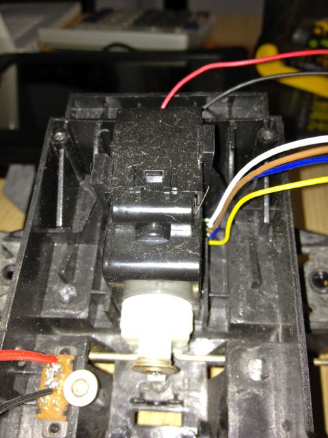
I have RC car with 2WD. The steering wheels in front are of angular movement(it moves only to certain angle) : http://i1265.photobucket.com/albums/jj519/soni991/RC%20Car/IMG_6672.jpg

What gadgets i have available :

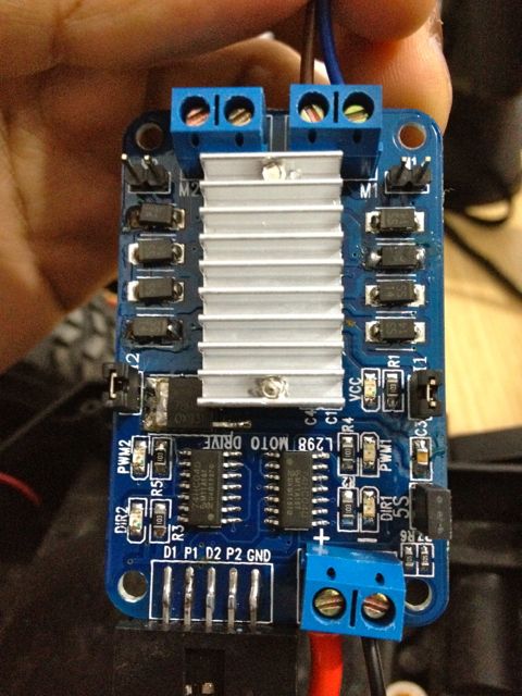
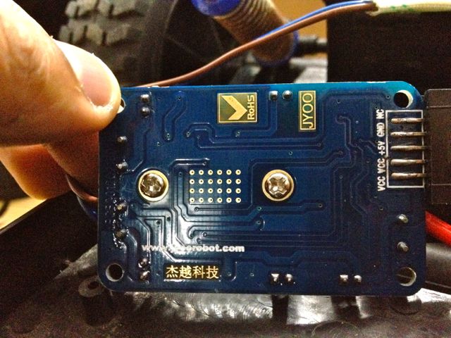
Picture: http://i1265.photobucket.com/albums/jj519/soni991/RC%20Car/IMG_6689.jpg

List:

1) MCU = Mega 2560.(not in picture)

2) HC-SR04 1pc

3) US-100 1pc

4) SD memmory card using SPI protocol 2Pcs

5)TCRT5000 2PC

6) Microphone 1pc

7) Light Sensor 2pc

8) Audio amplifier 1pc

9) Accelrometer 1pc 

10) Bluetooth 1pcs

11) USD to TTL 2pc

12) NRF 24L01 3pc

13) 10Pin to 6pin  AVRisp 2Pcs

14) logo sensor 1pc

15) CP 2102 USB to TTL 1pc (not in picture)

16) lot of jumper wires and solderless board. not in picture

17) HC-SR501.

More parts are coming so i would update those list.

So I am good to go with parts, how to start building smart robot with clean code.

Please can anyone tell me how do i configure the steering wheel of this car on arduino? i have put all the pics here: http://s1265.photobucket.com/albums/jj519/soni991/RC%20Car/ 

any one suggest any new parts please let me know so i can purchase it and use on this project.

1) First thing i need is suggestion about what parts i should include for the basic function in Version 1.

2) Second the Programing Code written from scratch with everyone contribution.

Hope i can have feedback from taleted people online.


**Bought Motor Controller: L298P **

Hi all,

totday i got the delivery of the Motor Controller L298P. It has 10Pinout the picture are below: 

Front: http://i1265.photobucket.com/albums/jj519/soni991/RC%20Car/IMG_6712.jpg

Back: http://i1265.photobucket.com/albums/jj519/soni991/RC%20Car/IMG_6711.jpg

I connected L298P and Mega 2560 as below:


L298P    ====    Mega 2560

D1--------------------- 7 Digital

P1--------------------- 6 Digital

D2--------------------- 4 Digital

P2--------------------- 5 Digital

+5 --------------    Vin pin( I need ask the L298P board have 2 pins of VCC so where should i connect that?is it safe i connect to Vin?)

GND------------------ GND point

Connected Battery 9.6v NiCad Negative point  to the " - " sign and the positive to an swith then to " + " of the L298P board respectively.

The code to test and do little Homework as below :

:


//Arduino PWM Speed Control:

int E1 = 5;  

int M1 = 4; 

int E2 = 6;                      

int M2 = 7;                        

void setup() 

pinMode(M1, OUTPUT);   

    pinMode(M2, OUTPUT); 

void loop()

  int value;

  for(value = 0 ; value <= 255; value+=5) 

    digitalWrite(M1,HIGH);   

    digitalWrite(M2, HIGH);       

    analogWrite(E1, value);   //PWM Speed Control

    analogWrite(E2, value);   //PWM Speed Control

    delay(500); 

  }  

}


:


I tried few experiment by changing value+=5 to -=5 and found that in case of +=5 the speed moved in from 255 to 0 and in case of -=5 the speed moved from 0 to 255.

i change the delay command to “500” to notice the change of movement where as this function i believe is depend on the programers choice.

i cannot figure out is how to i make the motor reverse movement. Please advice !

dir pins

If you would like your motors to go the other way, make your dir (DIRection) pins low instead of high. 

In terms of +=5 and -=5… That is just going to be the normal function of the “for-loop” you are using. In theory, it should be

for(i=0;i<255;i+=5)

–or–

for(i=255;i>0;i-=5)

DIR Pins?

Hi Chris sorry for my weak knowledge. Please elaborate how to make the DIRection Pin to low? is there way you can write an code line for me so i can insert and try on my board and give feedback.

Um… Ok…

digitalWrite(M1,LOW);

digitalWrite(M2,LOW);

Reverse Movement

I had updated the Code for the Reverse with help of Chris as below:


//Arduino PWM Speed Control:


int E1 = 5;  

int M1 = 4; 

int E2 = 6;                      

int M2 = 7;                        


void setup() 

pinMode(M1, OUTPUT);   

    pinMode(M2, OUTPUT); 

void loop()

  int value;

  for(value = 0 ; value <= 255; value+=5) 

    digitalWrite(M1,LOW);   // @Chris suggest for reverse movement

    digitalWrite(M2,LOW);   // @Chris suggest for reverse movement    

    analogWrite(E1, value);   //PWM Speed Control

    analogWrite(E2, value);   //PWM Speed Control

    delay(500); 

  }  

}


New Target:

With the existing code: i want to add the feature of moving ahead and reversing back to same location.

Please note the M2 is connected with the rear wheel and the M1 at moment is blank.

NOTE: (i am planing to add M1 in future just to steer upto certain angle rather then complete 360’ turn of wheels. as posted above the steering picture it can move in certain angle only. Pic Here :  http://i1265.photobucket.com/albums/jj519/soni991/RC%20Car/IMG_6672.jpg )

Something like this

Getting rid of the for loop, and doing things sorta “manually”, it will look something like this:


int E1 = 5;  

int M1 = 4; 

int E2 = 6;                      

int M2 = 7;                        


void setup() 

    pinMode(M1, OUTPUT);   

    pinMode(M2, OUTPUT); 

    pinMode(E1, OUTPUT);   

    pinMode(E2, OUTPUT); 

void loop()

  int value=255;  //use a scale of 0 - 255


    digitalWrite(M1,LOW);   // @Chris suggest for reverse movement

    digitalWrite(M2,LOW);   // @Chris suggest for reverse movement    

    analogWrite(E1, value);   //PWM Speed Control

    analogWrite(E2, value);   //PWM Speed Control

    delay(2000); 

   digitalWrite(M1,HIGH);   // @Chris suggest for reverse movement

    digitalWrite(M2,HIGH);   // @Chris suggest for reverse movement    

    analogWrite(E1, value);   //PWM Speed Control

    analogWrite(E2, value);   //PWM Speed Control

    delay(2000); 

}

Contribution and support: problem resolved

Hi all,

The features for moving forward stop and then reverse back in loop were very hard for noob like me at first but with help of Chris and Birdmun the code looks very simple and understable.


/* my rear wheel wires are connected to the M1 port of the Motor controller./

int P1 = 6;  //these are the Pin name on the motor controller connected to the digital pin no 6 of Mega 2560.                

int D1 = 7; //these are the pin name on the motor controller  connected to the digital pin no 7 on mega 2560.

void setup(){  

pinMode(D1, OUTPUT); 

pinMode(P1, OUTPUT);

}

void loop(){

analogWrite(P1,0);   // this is to keep the motor off by 2 second @birdmun suggested 

delay(2000);


/ this is for the Forward movement as the D1 is set to HIGH*/  

{

    int value;  //used as speed scale for the motor

    for( value = 50; value <= 255; value+=20) // this to smooth the movement of the wheels @Chris Suggested


      {

      digitalWrite(D1,HIGH);   // for forward movement  

      analogWrite(P1, value);   //PWM Speed Control

      delay(200);

      }

    }

    analogWrite(P1,0); // this is to keep the motor off by 1 second after above command is executed @birdmun suggested 

    delay(1000);

/* this is for the Forward movement as the D1 is set to LOW*/  

{

    int value;  //use a scale of 0 - 255

    for( value = 20; value <= 255; value+=20)

{

      digitalWrite(D1,LOW);   // for reverse movement @ Chris

      analogWrite(P1, value);   //PWM Speed Control

      delay(200);

      }

    }


  }


Add new Feature of Detection

Hi i want to add new feature of Detection via sensors.


The Sensors i had are 

1) Mini motor speed sensor 2 pcs

2) Ultrasonic sensor 2 pcs (HC-SR04 1pc & US-100 1pc)

3) Accelrometer 1pc

4) 3-axial Gyroscope (GY-521 MPU-6050) ipc

5) Light Sensor 2pc

6) logo sensor 1pc

7) Infrared Sensors (HC-SR501)

8) reflective Infrared sensors (TCRT5000 2PC)


Which one to use has good effect in detection and prevention for the nearby surrounding.

If can i use multiple sensors at same time to give more detail information about surroundings.

please leave your comment.

For object detection you can

For object detection you can use a few of those…

2) HC-SR04s are easy to use, nice general rangefinders. Like all ultrasonic sensors they don’t like plush upholstery and certain fabrics. The US-100 might be nice with it’s serial capabilities.

5) Light sensors are good for keeping bots from being under objects and for adding phototropic/photophobic behaviors.

6) Does sensor this find Nike swooshes and Gucci brandings? :wink:

7) Looks like a standard PIR sensor. Good for detecting motion but not good for localizing the object in motion.

8) Small and simple analog sensor but very short range. Useful for edge detection or maybe line following.

Now its time to learn code…

Alright, when we got your motors going, our goal was just to get the motors moving, get you started and check if you hardware was working. In doing that, we ran into a couple snags (i.e. learning the digitalWrite command and For-loops). Now that you are up and running, it is time to go back a bit and start learning code.

Basically, you want “code to read a sensor and let your robot drive around automously”. You are not going to find it. You may find some code you can modify, but you will need to know A) what to change B) where to find it in the code and C) how to change it. The bottom line is that you are going to have to learn some code.

Now, the over-all big-picture of robotics is to take something complicated and break it into very small steps. We can do the same thing when learning how to code. Instead of trying to jump ahead to a fully autonomous robot, you should spend some time figuring out each sub-section of code.

Here’s what I would do:

Start with 2 things, a servo and a HC-SR04.

  • Figure out how to make your servo move to a certain position
  • Figure out For-loops and how to move a servo a little each step in a back-and-forth "sweep"
  • Find some sample code for you HC-SR04 and test your sensor using the serial monitor. Also, make note of the numbers you are getting and how they relate to the distance of an object to the front of your sensor
  • Add a “check sensor” routine to your for-loop so you take a reading each time the servo takes a “step” through its sweep

At this point, you should have a pretty good idea of the basics of code. 

Lemme know if you have any questions.

Success !

Well after little big of google and support on shoutbox and some lookup of codes of existing projects i came up with function using ultrasonic sensors for detection.

but as at moment my front wheel are not connected to motor controller neither i am writing any command for it. the code looks like as below.


#include <Ultrasonic.h>

#define TRIGGER_PIN  13

#define ECHO_PIN     12

#define TRIGGER  9

#define ECHO     8


Ultrasonic front(TRIGGER_PIN, ECHO_PIN);

Ultrasonic rear(TRIGGER, ECHO);

int P1 = 6;                      

int D1 = 7;                        

void setup() 

{

pinMode(D1, OUTPUT); 

pinMode(P1, OUTPUT);

Serial.begin(9600);

}

void loop()

{     

//front distance calculation

float cmMsec, inMsec;

long microsec = front.timing();

{

cmMsec = front.convert(microsec, Ultrasonic::CM);

}

Serial.print(", CM: “);

Serial.print(cmMsec);


// rear distance calculation

float RcmMsec, RinMsec;

long Rmicrosec = rear.timing();

{

RcmMsec = rear.convert(Rmicrosec, Ultrasonic::CM);

}

Serial.print(”, RCM: ");

Serial.print(RcmMsec);


/* this is for the movement upon detection logic*/

if (cmMsec >= 45) // if ultra sonic see distance greater then 25cm go forward

{

int value(70);

digitalWrite(D1,HIGH);

analogWrite(P1, value);

}

if (cmMsec < 25) // if the Front Ultrasonic detects distance less then 10cm then Brakes.

{

analogWrite(P1,0);

if (RcmMsec > 25) // if the back distance is more then 25cm then go back

{

int value(70);

{

digitalWrite(D1,LOW);

analogWrite(P1, value);

delay(2000);

}

}

}

}

Button code using internal pull-ups


int inputState;


void setup()

{

  pinMode(2,INPUT);

  pinMode(13,OUTPUT);

  digitalWrite(2,HIGH); //<-- this turns the internal pull-up on

  digitalWrite(13,LOW);

}


void loop()

{

  inputState=digitalRead(2);

  if (inputState==0)

  {

    digitalWrite(13,HIGH);

  }

  if (inputState==1)

  {

    digitalWrite(13,LOW);

  }

}

4 inputs and out to the serial monitor


int contactA;

int contactB;

int contactC;

int contactD;


void setup()


{

  Serial.begin(9600);

  pinMode(2,INPUT);

  pinMode(3,INPUT);

  pinMode(4,INPUT);

  pinMode(5,INPUT);

  digitalWrite(2,HIGH); //<-- this turns the internal pull-up on

  digitalWrite(3,HIGH); //<-- this turns the internal pull-up on

  digitalWrite(4,HIGH); //<-- this turns the internal pull-up on

  digitalWrite(5,HIGH); //<-- this turns the internal pull-up on


  pinMode(13,OUTPUT);

  digitalWrite(13,LOW);


}


void loop()


{


  contactA=digitalRead(2);

  contactB=digitalRead(3);

  contactC=digitalRead(4);

  contactD=digitalRead(5);


  Serial.print(contactA);

  Serial.print("  “);

  Serial.print(contactB);

  Serial.print(”  “);

  Serial.print(contactC);

  Serial.print(”  ");

  Serial.println(contactD);

  Serial.println();

  delay(250);


}


Detecting low battery

To detect whether your robot is running low on battery, connect a voltmeter chip across the battery leads and read the value to the microcontroller. When it drops below a certain threshold, it will know to charge up somewhere :slight_smile:

Michael

http://hirobotblog.blogspot.co.uk/

trouble writing code for the steering

hi all i am having trouble writing code for the steering.

the code is below:


  #include <Ultrasonic.h>

  #define TRIGGER_PIN  5

  #define ECHO_PIN     12

  #define TRIGGER  10

  #define ECHO     11

  int D1 = 6;

  int P1 = 7;

  int contactA; // contact A is the sensor which turns signal to ‘0’ when the wheel is all the way to left.

  int contactB; // contact B is the sensor which turns signal to ‘0’ when the wheel is all the way to left.

  int D2 = 8;

  int P2 = 9;


Ultrasonic front(TRIGGER_PIN, ECHO_PIN);

Ultrasonic rear(TRIGGER, ECHO);


  void setup()

  {

    Serial.begin(9600);

    pinMode(2,INPUT);

    pinMode(3,INPUT);

    digitalWrite(2,HIGH); //<-- this turns the internal pull-up on

    digitalWrite(3,HIGH); //<-- this turns the internal pull-up on

    pinMode(13,OUTPUT);

    digitalWrite(13,LOW);

    pinMode(D2 , OUTPUT);//this is for the front motor

    pinMode(P2 , OUTPUT);//this is for the front motor PWM

    pinMode(D1 , OUTPUT);//this is for the rear motor

    pinMode(P1 , OUTPUT);//this is for the rear motor PWM

  }

  void loop()


{ // steering angle detection

    contactA=digitalRead(2); //yellow

    contactB=digitalRead(3); //blue

  Serial.print(contactA);

  Serial.print(" A “);

  Serial.print(contactB);

  Serial.print(” B “);


   {if (contactA == 1 and contactB ==0)

    {

     digitalWrite(D2,LOW);

     analogWrite(P2,0);

    }

    if (contactA == 0 and contactB ==1)

   {

     digitalWrite(D2,HIGH);

    analogWrite(P2,0);

    }  

    }


  //front distance calculation


  float cmMsec, inMsec;

  long microsec = front.timing();

  {

    cmMsec = front.convert(microsec, Ultrasonic::CM);

  }

  Serial.print(”, CM: “);

  Serial.print(cmMsec);


  // rear distance calculation


  float RcmMsec, RinMsec;

  long Rmicrosec = rear.timing();

  {

    RcmMsec = rear.convert(Rmicrosec, Ultrasonic::CM);

  }

  Serial.print(”, RCM: ");

  Serial.print(RcmMsec);


  /* this is for the movement upon detection logic*/


  if (cmMsec >= 45) // if ultra sonic see distance greater then 45cm go forward

  {

    int value(70);

    digitalWrite(D1,HIGH);

    analogWrite(P1, value);

  }


  if (cmMsec < 25) // if the Front Ultrasonic detects distance less then 25cm then Brakes.

  {

    if (RcmMsec > 25) // if the back distance is more then 25cm then go back

    {

      int value(70);

      {

        digitalWrite(D1,LOW);

        analogWrite(P1, value);

      }


    }

     if (RcmMsec < 10) //if the back distance is less then 10cm then stop

            {

              analogWrite(P1 , 0);

          if (  //here i want to write command for the steering wheel so it can steer to left with steering detection and then go ahead)      


  }

Please describe your error

Please describe your error (compiling, functioning ?) if you want help.

Is this the bit of code you

Is this the bit of code you are having trouble with? Can you describe the problem?

   {if (contactA == 1 and contactB ==0)

    {

     digitalWrite(D2,LOW);

     analogWrite(P2,0);

    }

    if (contactA == 0 and contactB ==1)

   {

     digitalWrite(D2,HIGH);

    analogWrite(P2,0);

    }  

    }

Just based on a quick look, this code will detect if the steering swtiches have detected that the steering wheel is all the way left or all the way right. I assume D2 sets the direction for the motor to go, and P2 sets the speed. You have analogWrite(P2,0), which will stop the motor. Is that what you want?

Correct

Yeah that is correct ! i am not sure if D2 was really required there! simply the (P2,0 ) could have done the job of switching the motor OFF upon max angle. my issue after making the turn signal then the steering need come back to center maybe after some millisecond or a second. what can be that command 

http://i1265.photobucket.com/albums/jj519/soni991/RC%20Car/IMG_6698.jpg

http://i1265.photobucket.com/albums/jj519/soni991/RC%20Car/IMG_6697.jpg

these are the schematic of circuit which i need use for detection of the angle. i am currently using 3 wires out of it. the white one i am not using. The brown is connected to grd and the yellow and blue is sensor input which detect the 0 upon contact. i think the white wire is the one used to bring the weel to center. CTC also thinks the same so i would try in evening.