

I have written this to assist any other builders out there who have been thinking of using Maker Beam. I decided that I wanted to build a more rugged superstructure for my robot. The initial Meccano based one suffered from bending with vibration and impacts with chairs and other robot level hazards. I also wanted to progress with an arm and needed a solid structure to base it on. Finally I wanted to be able to remove the superstructure as a unit and place it on a more rugged powered base for outside traveling. I have purchased a thumper 4 x 4 for this sometime in the future, however now the T-rex has been announced Hmmmmmmmmmm.......
Enough dreaming back to the project.
I decided that Maker Beam could be the go as I have no access to engineering facilities any more nor to a 3d printer. Maker Beam would give me the ability to easily change sensors, servos, and other peripherals, and seemed it would allow me to make significant changes to the design if required.

Not sure what pieces I would need I ordered the "Starter Kit". This arrived neatly packaged with the aluminum beams, bolts, corner brackets and a good quality nut driver. (Picture 1) Inspection revealed that my kit was missing the nuts, I called my supplier, Technobots, to ask if I should contact Maker Beam as it was a sealed package from the manufacturer. Quick as a flash they said "we will pop another bag of nuts in the mail" which arrived the following morning. WOW - incredible service - I'll be using them again.
The system works by having square headed nuts which slide in the channels of the aluminum beams with the thread sticking out from the slot. Corner brackets are then placed on the protruding thread and secured with a nut. This leaves the nut on the outside of the bracket which may not be esthetically pleasing to some folks.

I began by laying out the parts for one side of the structure, checking dimensions and using a square to ensure intersecting beams were at 90 degrees where required. (Picture 2).
I chose to have some beams at 45 degrees to provide diagonal bracing and also to allow the mounting of a rear facing LCD.
I then placed the corner brackets in position to ensure that there were no conflicts with brackets trying to overlap each other and to determine how many screws I needed to insert into each beam. (Picture 3 ) Where ends of beams are "closed" by another beam you have to disassemble your construction to get more screws in at a later date.

Then came the assembly of the side. I found the best way was to add all the nuts just "finger tight", and then work from the bottom rail with the square and the nutdriver tightening one nut on each "leg" of a bracket to ensure everything fitted in the right place. There is some play in the screw holes in the brackets so just fitting them does not ensure a true 90 degree or 45 degree joint. After I was happy with all the positions I tightened the second nut on each bracket leg. I then had one side frame. I assembled the other side frame ( in reverse) following the same procedure, checking the two frames by placing them on top of each other. (Picture 4 )

The next step was to assemble the sides with the cross pieces as shown in the photo. ( Picture 5)
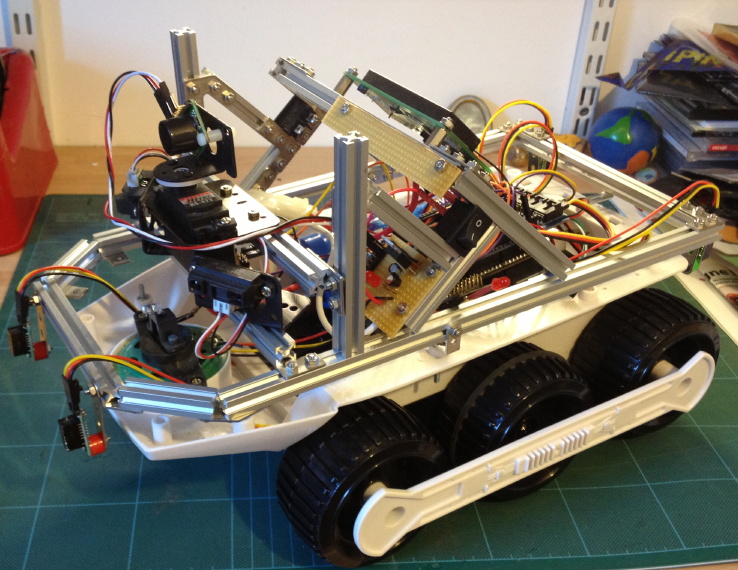
Once again I went through the squaring up procedure before completely tightening up all the brackets. Then I fitted the other cross beams, adding the servo and sensor brackets.. The assembly was then ready to mount on my "big track" chassis.


I used the angle brackets supplied with the kit, and being able to slide these up and down made the job easier to match up with existing holes in the chassis. I then added the front beams to hold the IR "bump" sensors. ( Picture 6 )

I have also been able to mount a square switch of the "press in" variety by adjusting the beam spacing accurately. (Picture 7 )

Despite all my careful planning I have still had to add screws to beams which have their ends "blocked" by other beams requiring some degree of dismantling but I've now become quite good at that.
Summary;
The structure is very solid and rigid and meets my original aims. Its possibly heavier than I would like and is over engineered for a bot this size however I am pleased with the result ands its flexibility to allow change in the future. It's much more rigid that previous Meccano structures.
The starter kit had more than enough bits to do what I wanted, however I recommend buying some of the hex stand offs to facilitate the mounting of circuit boards. ( Used for the LCD display )
Disadvantages;
In the standard system there is no brackets for greater than 90 degrees. that is if you wanted to produce the base for say a hexagon shaped robot or where I constructed the front rail on my robot there is no easy solution. (Picture 9 & 10 )


Overall I enjoyed using Maker Beam and found it straight forward to build a sound structure without having to use any drilling, cutting or filing tools. It will easily allow the fitting of side panels for outside protection and appearance at a later date. The work I put into arms or other structures can now be easily transferred to a different more rugged mobile chassis when the need arises.