Make your own "FTDI cable" for $5

DSC00891_resize.JPG

I read on the Arduino forum about using cheap Nokia data cables as a compatible "FTDI cable". I decided to have a look and started to shop around for a compatible cable. The best candidate seems to be the CA-42 USB2.0 Nokia Data Cable and I ordered this one: http://www.dealextreme.com/details.dx/sku.45715 from Deal Extreme for $4.40 with free shipping. It comes in a box with a driver CD, so you don't have to browse all over the internet to find drivers.

This is how it looks like:

DSC00887_resize.jpg

The nice part of this cable is that the blue plastic casing is not glued, so with a knife I pried it open. Inside, I found a small PCB with a black blob and... lucky me, the pins are already labeled! It has GND (the label is covered by the blob), Rx, Dtr, Tx and Vcc.

DSC00888_resize.jpg

Only GND, Rx and Tx were used, so I needed to ditch the original cable and make a new one. For this purpose I bought a 6 wire phone cable, about 2 meters long (good for 3-4 cables) for $1 and some crimp pins and 6 pin housings, $0.40 a set. 

I stripped one end of the phone cable and there were 6 colored wires: white, black, red, green, yellow, blue. I need only 5 wires, so I cut off the white wire. Then I crimped 5 pins on the remaining wires and I plugged them like this (from left to right):

  • Blue    - Dtr
  • Yellow - Tx
  • Green  - Rx
  • Red     - Vcc
  • nothing
  • Black  - GND

Then I stripped the other end of the cable, cut off the white wire, then started to solder the remaining wires in order (from left to right):

  • Black  - GND
  • Yellow - Rx
  • Blue   - Dtr
  • Green - Tx
  • Red    - Vcc

The Dtr pin on the little board had a red wire jumper to a pin on the back of the board. I removed that wire before soldering the Blue wire instead. When soldering the Rx and Tx wires you need to be careful and switch them, so the Rx pin from the microcontroller will go to the Tx pin from the FTDI chip and the Tx from the microcontroller will go to the Rx pin from the FTDI chip.

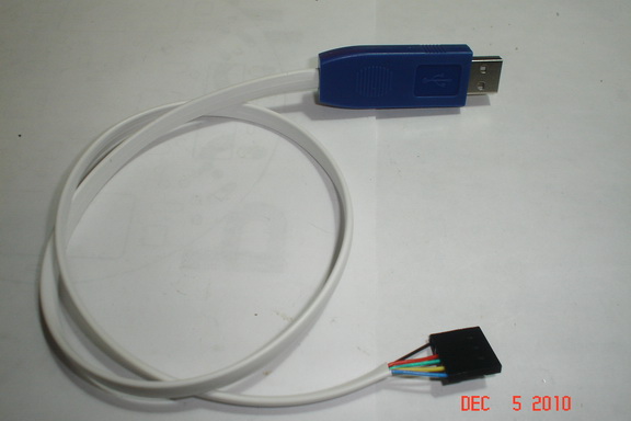
This is how the cable looks now:

DSC00889_resize.jpg

Then I placed the little board back in it's plastic casing and closed it.

DSC00890_resize.jpg

The only thing that is missing are the Rx-Tx LEDs, but we'll live without them.

Before I can use the cable I need to install the driver. I put the CD in and browsed the folders to find a Windows 7 compatible driver. I didn't, but I found a Vista driver and installed that one. After the install finished, I plugged the cable in the USB port. New hardware was detected and the driver loaded. It shows as a "Prolific USB-to-Serial Comm Port" and was allocated the COM8 port. So it is not a FTDI chip, but another chip that does the same thing.

Will Arduino IDE work with it? Let's see. I took a µBotino board and plugged the cable in the FTDI header. The power LED came on and the already loaded Blink program started to run. So far so good. I started the Arduino IDE and loaded another Example sketch, selected the serial port COM8 and clicked the Upload button. The pin D13 (red) LED flickered for a moment and then went off. After a little bit, the "Done uploading" message came in the IDE, so I was sure the uploading was done. The Blink sketch was not there anymore, because the D13 LED wasn't blinking. I loaded the Blink sketch and clicked on the Upload button, then, after seeing the "Done uploading" message, the D13 LED started to blink again! Success!

DSC00892_resize.jpg

As you can see, this is an easy and cheap way to make your own FTDI cable and you can use it as a USB-serial cable for any project you have.

Cheers!

great tutorial :slight_smile:

great tutorial :slight_smile:

smart solution!

I bet this post will save some USD to many users in the forum!


Good find, thanks for sharing

Did you verify this is a genuine FTDI chip from the computer?  If so that is a good deal considering what the chips cost alone.  Looks like the cable can be useful with only the Rx, Tx, and GND pins.  DX has some sweet deals including $6 oscilloscope probes :slight_smile:

It’s not a genuine FTDI

It’s not a genuine FTDI chip. In Windows 7 shows up as “Prolific USB-to-Serial Comm Port”. However, it works. All you need is a serial Comm to communicate with the Arduino board. It doesn’t matter what device provides that Comm port. It may be RS232 Comm port, or FTDI chip, or another AVR configured to work as a USB to serial interface (see the Arduino Uno board). So even a Prolific chip with the proper driver works. Of course it’s not actually a real FTDI cable, but works as one.

Very nice. Will save people

Very nice. Will save people some money and so might encourage others to try Arduino. This plus my inverter tip https://www.robotshop.com/letsmakerobots/node/21245 and you should be able to use it on a Picaxe. 

Prolific makes good chips

Prolific makes good chips too.  Tend to have good driver support and work with win7 x64

My cheap suggestion costs 4

My cheap suggestion costs 4 times as much, but includes a free GPS. Currently (Dec 2010) there is a vendor on Amazon selling the Pharos GPS-500 with Microsoft branding (was packaged with Streets) for $19 delivered, including the USB adapter and a USB extension cord. It will come in a plastic case that says Microsoft on it. Carefully crack that open to expose the GPS. Lay it chip down with the connector toward you. The 2nd lead from the left is for 3.3v or 5v (I have had success with both), followed by GND, GPS Tx and GND. Wire those 4 and it will start spewing NMEA strings at 4800 baud. I am pretty sure that GPS Rx is 1st lead on the left. I don’t know that it listens for commands, but that would be important if you want to use the USB adapter that came with it to make an FTDI cable. Just match up which would connect to what using the GPS pinouts and you are good to go!

Since using the words "FTDI

Since using the words “FTDI cable” created confusion, I updated the tutorial to specify that it is not a true FTDI cable, but a compatible cable that does the same thing. In the Arduino community, the words “FTDI cable” are used more like a type of cable that can be used to program Arduino boards that do not have the FTDI chip on board, so people are looking for that type of cable and most of the time they are overlooking similar cables that do the same thing and are cheaper. The FTDI chip has a lot of unused functionality and may be worth it’s price, but to achieve a simple USB-serial interface with auto-reset it is overpriced. I have tested the cable with the xBees and it works perfectly (needed an Tx-Rx swapping to connect to my xBee regulated board, since this board already has those pins swapped). Also, the little board inside the cable has another wire jumper on the back of the board, that may be for other pins usually used on a serial interface (RTS, CTS) so people can use them if needed. There are many similar cables that do not have those pins brought out and you have to poke around with the DMM while using the adapter to find out what pin is what.

Works great

I made mine, and works pretty good, so thanks very much =DDD*

Cool! Cheers!

Cool! Cheers!

Arduino Pro Mini??

Does this cable work with the Arduino Pro Mini??  I made one, hooked it up and everything LOOKS like it is working (all lights are on, etc.) but the arduino program will not upload my sketch to the board.  It has the same connections as the rest of the Arduinos, but this is the only thing that I can see that can be the problem.

The code will not load if:1.

The code will not load if:

1. the Tx and Rx pins are not swapped.
2. the board does not autoreset.

Check the cable with a different board, if it works, then press the reset button on the board manually. I have this problem with one of my boards. If the cable does not work with another board (or try it on a breadboard with a microcontroller that you can get from a regular Arduino board) then try to swap the Rx and Tx wires on the cable. This should work. If it doesn’t, then… it is a bad cable.

**pro mini **
I swapped the tx and tx. The only other board I have is the duemilanove and I’m not sure how to hook this cable to it. The pro mini is supposed to autoreset. I have tried to push the reset button at many different times, as the arduino help boards suggested. None of them work. I checked continuity of all of my wires. They all check out and all are getting the correct voltages out. Do you have any other suggestions or did I just get a bad cable? I just got it in the mail 2 days ago but that would be my luck.

question

the usb from a genius “mini traveler” mouse is compatible ?

I got mine today and its

I got mine today and its working with Windows 7 x64.  It looks like the high voltage level of Tx is about 3.6V.  I’m also using the original cable as it already has Gnd (blue), Tx (white), and Rx (green) -> I just need to make a header for it.

I’ve used my cable a bit

I’ve used my cable a bit (not extensively) with both Windows 7 32 and 64 bit OSs and I’ve experience a Blue Screen a couple of times with my 64-bit system, it seems likely an issue with the driver interacting with the device.  Anyone else experienced this??  For me it happens when setting up a new connection in a terminal program, Tera Term 4.52 Software.

It may be happening when I close a terminal without first closing the connection and reattempt a connection with another terminal instance.  I’m thinking of ordering a few more unless they are causing problems for other people, so any feedback is appreciated.

I use it regularly with

I use it regularly with Windows 7 64-bit, and it has never been a problem.

I’m using it with the Arduino IDE v0019. I don’t use Tera Term, so I don’t know if there’s a problem with the cable working with that software. I open and close the Arduino terminal at will with no ill effects.

Thanks ignoblegnome,Thats

Thanks ignoblegnome,

Thats good to know, I will get a few more then.  Using female crimp pins and 3-pin connectors (I picked some up from pololu.com) makes these very compact for a basic 3-wire serial connection, and I found a good crimper for $9 at radio shack, score.

How can i identify the 'dtr’

How can i identify the ‘dtr’ pin on my cable? My cable is different than yours - https://www.robotshop.com/letsmakerobots/ode/33342