

All for my new robot project - a Hexapod. I did a quick 3d renedering on how it is going to walk. If I have anything of interest to show I'll make a new 'robot' entry :)
https://www.youtube.com/watch?v=VbgkODkgif4
All for my new robot project - a Hexapod. I did a quick 3d renedering on how it is going to walk. If I have anything of interest to show I'll make a new 'robot' entry :)
https://www.youtube.com/watch?v=VbgkODkgif4I see you have an obsession
I see you have an obsession for servo motors ;-). Hexapod sounds like fun - can’t wait to see what you come up with!
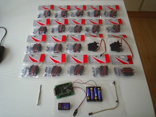
4 DD cells, 20 servos, I
4 DD cells, 20 servos, I like it 
Shouldnt this be a blog-post? Well, whatever!
What is your servo controller?
Will your hexa be blind?
How are you going to hook them up? I have some thingeys to strap onto servos turning thingey, if interested!
wow! so many plastic bags
wow! so many plastic bags all together!!
I am interested too in which servo controller you’ll be using for your project
Cells
Dude, those are AAs. Not DDs. Don’t you know anything about bra sizes?
On that point, assuming these are stock R/C servos, they will draw about 300mA each under load. That means you need more juice. Assuming you lift 3 legs at a time off the ground. Let’s guess they run 100mA each with no great load. you’re into 600mA. Let’s assume you drive forward with three legs at a time. Not at full stall (obviously). You’re into 900mA. 4 good AAs are only going to offer 1500mA. (OK so far.) BUT, drawing 600-900mA from your pack is going to cause a voltage drop on your PIC and it will brown out.
I found this the hard way with my biped. Only powering 2 servos at a time the uC would reset. Could I suggest you consider a R/C racing pack (7.2V rechargable NiCd)? I would also consider a drive circuit with, maybe, 4x 7805 regulators whose INPUTS are in parallel (for God’s sake don’t put the outputs in parallel - unless you want the smoke to get out). Three of them would supply each alternate pair of legs on the tripod (assuming you adopt a dual-tripod gait) and one for the CPU.
Look at my servo controller board. See the 3x voltage regulators at the back and the SODDING BIG HEATSINK? You think that’s for decoration?
Experiment: drive one servo from your controller. Write a program which increments a counter each time the MCU powers up. This counter should be stored in EEPROM. Put a load on the servo (by grabbing it with your fingers). Grab the servo a few times and then read back the EEPROM contents. You will have found that each time the MCU resets due to brownout, the counter increments.
Ask me questions.
NB - “turney thingies” are knowns as “horns”.
Wow! 20 servos?! Could
Wow! 20 servos?! Could this not be done with 9 servos? 3 servos to turn arms left & right and one on each end of each arm to move "foot" portion of the leg up and down like a piston? Just a thought. Looks like a great project. Looking forward to seeing the results.
It would seem from the
It would seem from the picture, that he has a 9V battery to power the uC :-).
Another way to get the power needed for all the servos is to get a DC-DC converter like the one at http://focus.ti.com/docs/prod/folders/print/pth08t220w.html. It delivers a max of 16 A.
In Denmark "horns" are known as "turney thingies"! 
"4 DD cells, 20 servos, I
"4 DD cells, 20 servos, I like it :)"
- Indeed it are 4 rechargable AA cells, not DD
"What is your servo controller?"
My servo controller will be this the serial-servo-controller-32 (SSC-32). It can handle up to 32 servo’s at a time, simultaneously. It is a very powerfull board with open source software. The microcontroller which is going to give the serial commands to the SSC-32 will be the Atom Basic Pro 28 (used earlier in my Rebel robots).
"Will your hexa be blind?"
No it won’t be blind, but for the time being I will first try it to make it walk. Baby steps Once I succeeded in making it walk and turn I will ad a pan and tilt system with a ultrasonic sound sensor mounted on it.
"How are you going to hook them up?"
I make everything with some light wood “triplex” (don’t know what it is called in english?) First I will design everything in some cad program (already started with that) and then cut everything, and then the fun can begin.
"BUT, drawing 600-900mA from your pack is going to cause a voltage drop on your PIC and it will brown out."
First, the uC won’t be a PIC but a Atom Basic Pro, and indeed I will power the uC with a 9V battery and the servo’s with 4 AA cells (maybe a 7.2 pack in the future). I hooked up all 20 servo’s and moved them at the same time, everything worked fine, so no problemo. If it turns out that it will reset, I wil buy more batteries
"Could this not be done with 9 servos?"
I want 3 DOF (degrees of freedom) for each leg. So the bot can lift it’s leg, turn the leg ford and back and also adjust the body height. It has 6 legs, so 6x3 = 18 servo’s. Then I need 2 more servo’s for the pan and tilt system I will make for it’s “head”. So it’s head can move left, right and up, down.
Juice…
"BUT, drawing 600-900mA from your pack is going to cause a voltage drop on your PIC and it will brown out."
First, the uC won’t be a PIC but a Atom Basic Pro, and indeed I will power the uC with a 9V battery and the servo’s with 4 AA cells (maybe a 7.2 pack in the future).
Noted. Force of habit. When you’re used to the best, it’s hard to accept that some folk still use inferior technology
I hooked up all 20 servo’s and moved them at the same time, everything worked fine, so no problemo. If it turns out that it will reset, I wil buy more batteries
Of course you can make them move, but can you make them all lift 100g at the same time? Let me put it another way: I can make the windscreen wiper motor of a car move from 4 AA cells, but I doubt it would carry around a 190lb adult.
I don;t think you need worry about teh servos “reset”. The analog control board will definitely brown out under load, but because it’s analog, it’ll pick up again right where it left off and you’ll probably not even notice.
You know what? You might be better off with four DDs! Here’s the paradox: you’ll probably need more power to lift the batteries!
So I made a few quick
So I made a few quick sketches today of how I want to make to robot look. And how the mechanical part is going to work. After putting my ideas on paper I downloaded google sketchup and made a 3d model of it. Then rendered the google sketchup with pov-ray. And I must say, I’m impressed on google sketchup / pov-ray. I looks really nice IMHO. Well… see for yourself
Hopefully my robot will look like the image above when finished. Back to the drawing board for a nice 2D cad file with metrics, so I can begin cutting the wood (by hand  It would be really nice to have a CNC for this project, ah well, you can’t have everything).
Hmm, I should make this a blog or robot entry. It’s getting out of hand.
That is looking nice. I see
That is looking nice. I see you’re only using two screws to attach each of the first two servos for each leg to that block that connects them. Will that be strong enough? It seems like this robot could end up weighing a decent amount, and I’d be worried that it would rip those screws out of the block.
Power-wise, BOA may be right that you’ll need something more hefty (I think the 7.2v R/C car pack sounds perfect), but it doesn’t hurt to try it with the 4 AAs and see what happens.
This definitely is coming together enough that it would make more sense to post it as a robot. You’ve got CAD pictures and everything I’ll have to give Google Sketchup a try.
Dan
EXCELLENT
First, yes. That is brilliant looking and I hope you see it through.
Second, “POV-ray”? Does Sketch up render in POVray? I’ve been using POVray for years and did not know this.
Last, Robot or blog. Hmmmm… You got do both. You’re getting loads of good feedback here. You could make a “robot” and put a request on it that anyone who wants to comment comments to the blog.
I have found this problem with my robots as well. the Rboto pages becoem cluttered. I think we may need to make an executive decistion. I would like to see roboteers have editorial rights over their own robots, so they can tidy up the pages. The danger is that some useful information might get lost.
I’ll put it on the agenda for the next admins meeting.
"I would like to see
"I would like to see roboteers have editorial rights over their own robots, so they can tidy up the pages" Well they already have! JUst click edit!?!
Are you talking about the comments? Well - we cannot edit them, excactly; Someone may link to them. Click on the headline of a comment. You get the URL with that comment. I sometimes link to that, and should do it more often. Say when someone is making a good remark on a component, I / we ought to enter the component (that anyone can edit btw) - and write "Here is a comment related…"
Robot or blog?
If you feel youmostly are going on about your life, what you think of stuff etc, it is a blog. If you are focusing on a robot-project, it is a robot that you should enter.It is absolutely to prefer to enter a robot as a robot!
Have a look at my 360bot- project. I am not showing all images on the page, but link to an online album. Considering what you do make keep the page cleaner.
And people commenting can also help, by refraining from too many non relevant postings etc
I’d love to have the system to use multiple pages etc, but it is a thin walk between feutures and usability. Heck, we have people who find it difficult to enter a robot as it is! (And I am going to make some instructions on that some time)
Hey - btw; Your robot looks
Hey - btw; Your robot looks awsome!
And to what I wrote above; Notice that you can chose how so see the comments!
Bearings
I meant to ask: What are you going to use for bearings for the "other" side of the servos? You know at the bottom of the six "main" servos?
Extrude
If you can find some plastic or aluminium box section extrusion about 30mm by 20mm (about the width of the servo body, but slightly taller) and fit the servos into it, that gives you and nice “bottom” (!) that you can bore into and stick a bolt through.
I did this once with PVC and it was very very good. The biggest pain is cutting the square hole for the servo.
I couldn’t find the extrustion again, so I used 30mm U-section aluminium extrusion. It was less good and much more difficult to cut the holes.

