Lynxmotion SES V2 Hexapod Robot

Hi All,

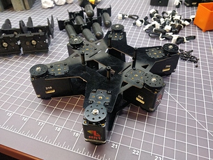
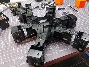
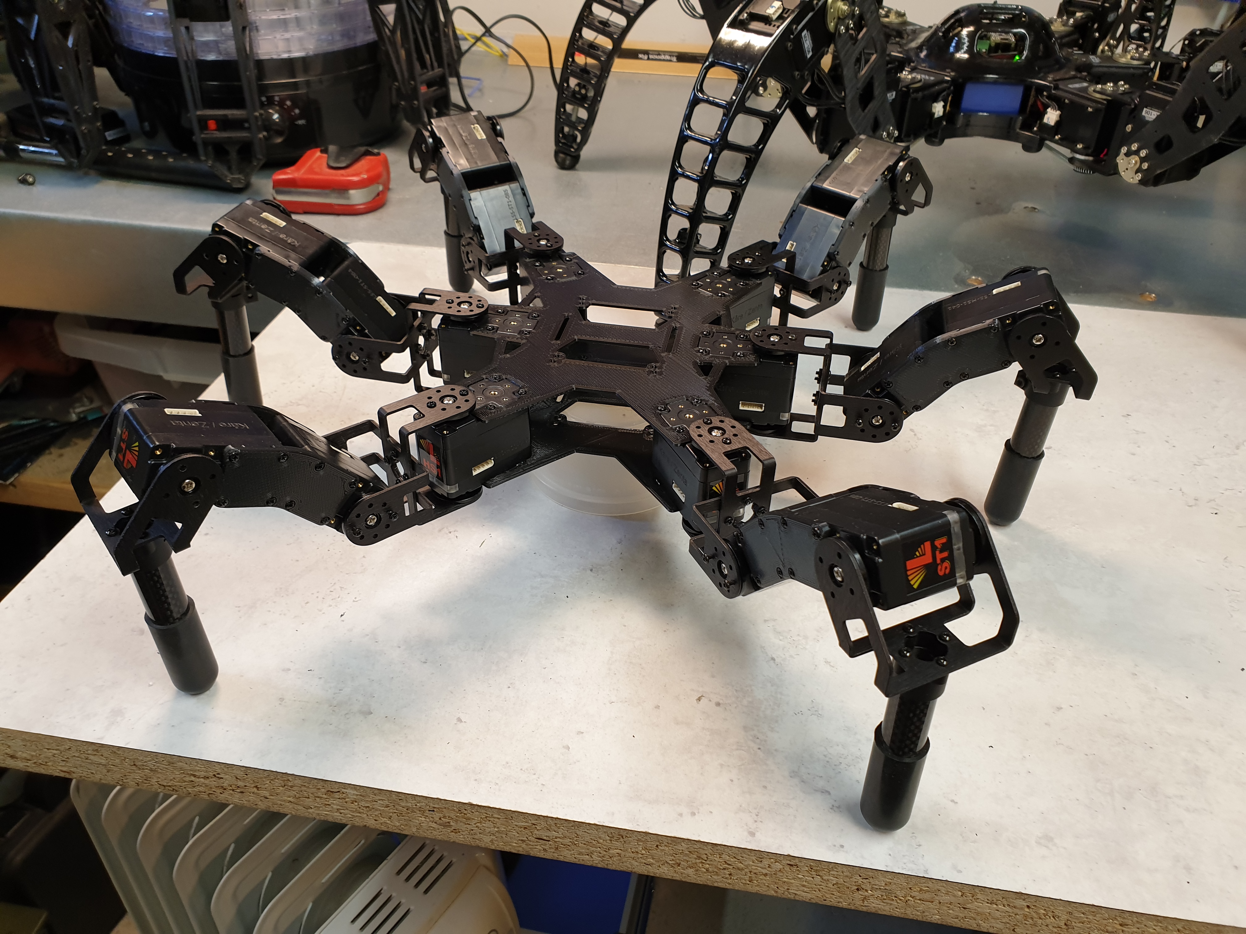
Here is the initial design I came up with but nothing is fixed and feedback is greatly appreciated…!! (I would add, required). This was cut with cheap / glossy 1.5mm G10 (fiberglass) for fitment testing.

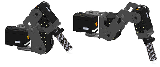
I went for a simple leg design (but many options there) using the standard Lynxmotion parts.

I’ve also put another version on the Lynxmotion Wiki - Sample Leg A.

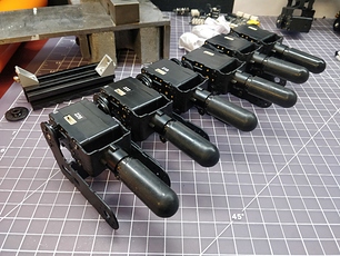
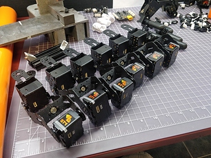
While i was assembling:


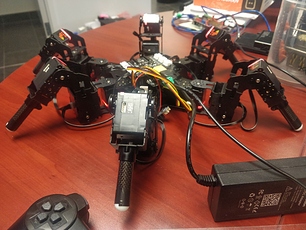
Once assembled:

Let’s start the fun :slight_smile:

4 Likes

Hey Guys!

The hex is looking Good! Do we already have a name in mind? :wink:

Clear description of the scope Coleman. I think the new servos with feedback, together with the powerful Pi, will open more possibilities and will push the capabilities further then we could reach before. Let’s see what this puppy can do!

Hey @kurte, long time no see! I’ll send you a pm to keep this treat on topic.

Xan

3 Likes

No names in mind at all yet, same as the physical designs. Figured we’d compile a list of all naming suggestions and vote at the end?

Yes this should be a lot of fun. Will be interesting to see where all we take it.

Again sorry if some of this is maybe a bit off topic, but may might help to look at starting points.

Over the last many years most of the Robotics stuff I have done was with using smart servos by Robotis, mostly with Trossen Robotic Hexapods. (Actually the last couple of years spending most of my play time working with Teensy Micro-controllers by PJRC).

Earlier I played around and ported the Phoenix code to run on Linux controllers such as RPI, Odroid, UP, BeagleBone black… My github project was/is always in a state of disarray but is up at:

Also during that time frame, another Trossen Robotics member, created a monster hexapod and a ROS stack for it. His project for the ROS stuff is up at:


More on this hexapod at: http://forums.trossenrobotics.com/showthread.php?6725-ROS-Hexapod-project-Golem-MX-64-4dof
Note: a few of us worked with KevinOchs at made the code work on the PhantomX (Trossen standard hexapod) with either RPI or Odroid. There is another thread up on their forum if anyone is interested.

Now back on topic. This looks like it will be a lot of fun. I do need to more familiar with these servos! Things like, What type of feedback can I get from them? I assume things like current position, maybe voltage, maybe temp? What about how much force or torque they are under…

Sounds like old times

2 Likes

Excellent!

Feedback:

  • Position in puse or tenths of degrees
  • Voltage in millivots
  • Temperature in tenths of degrees Celsius
  • Current in milliamps
    … and a lot of other queries (speed, origin offset, angular range, etc. etc.)

We’re working on calculated torque since there’s no “torque sensor” onboard. We’ve had success implementing CH and CL command modifiers which cause the servo to halt or go limp if the current ever goes beyond the value (possible easy solution for terrain adaptation).

https://wiki.lynxmotion.com/info/wiki/lynxmotion/view/lynxmotion-smart-servo/lss-communication-protocol/

We’re waiting for Matt Denton to come back from vacation and participate too (he was part of the LSS BETA)

Hi everyone!

LSS Servos
I have been working on the Lynxmotion Humanoid robot for about 2 months now and I can say they have come a long way since the initial beta. They are performing great in my humanoid robot so I don’t think you will have any issues getting good performance for the hexapod. They’ve put a lot of work into new commands for smooth motion and torque control. I especially like turning off the typical RC-like servo motion control and enabling the IIR motion filter. I can blast position updates and get better motion control for humanoid dynamic control. The motion is so much smoother! To illustrate, I coded one arm to follow the other (in limp mode) and there was no latency, it even mirrored the acceleration of gravity smoothly when I drop the arm at the end.

Joint Compliance
I believe there is no better user interface for a robot than direct human-robot interaction with compliance. Thanks to Sebastien for implementing some feature requests for torque control I was able to create a Compliant Joint controller even my 6 year-old naturally understood. :slight_smile: This also worked great for auto-detecting obstacles or itself! So even before any differential equations or Jacobians this robot is safe to operate without hurting anyone or itself. These features greatly improved compliance response (LSS commands in bold):

  • Disabled RC-like motion control (EM0), enabled IIR filter.
  • Using IIR filter pole count (FPC) to control smoothing of position updates. Makes a big difference! I also change this in realtime to adapt to conditions.
  • Controlling response stiffness (AS,AH) in real-time (ex. less jerk transitioning in/out of compliance modes)
  • Controlling max torque using MMD commands allows active compliance where the joint resists or supports itself while still being manipulated by human.
  • Reading back position and current. Current seems accurate and directly proportional to joint torque.
    Servo LED Legend: blue=holding, red=limp (passive compliance), pink=active compliance (powered but still compliant).

Humanoid Dynamic Control
I then added Gravity Compensation with an IMU, Kalman filter and Inverse Dynamics to better determine external forces for compliance by subtracting gravity forces. Not perfect yet but it is able to hold its leg straight out which shows the inverse dynamics is increasing torque to those joints and still able to detect the force of my hand. It’s not detecting ground contact forces yet so it wont stand on its own. I am now in the process of implementing the balance and walking humanoid dynamics.

3 Likes

@kurte @xan @zenta @cmackenzie Regarding the hardware, is the design above good to go to get started? We want to ensure we’re all working on the same hardware. We’ll pack them up and ship them out when we have everyone’s “go”.

Good Morning,

My guess is the underlying hardware is probably good. Obviously others here who have experience with these servos can probably give a much more definitive, that looks like it will work…

I guess one of the more interesting question will be on what direction we take with this hardware, in the software and what electronics and sensors and the like are you expecting to use and if this part will be standardized.

For example, I know you mentioned ROS2, which I played with a little… But as usual with ROS forgot everything…

Awhile ago I was trying to get myself back into ROS, and at the time felt like trying to understand ROS through KevinOs ROS stack was not probably the best way to understand ROS as it felt like he was trying to fit a square peg in a round hole… So I purchased a Turtlebot3 Waffle and later cobbled together most of a burger to try things out… Unfortunately I got distracted back to trying to get the underlying electronics to work better and play with the underlying controller software and did not spend enough time playing with ROS.

During that time I was working back and forth with some of the ROS people at Robotis, who worked on their Turblebots plus wrote the ROS book you can download from: https://community.robotsource.org/t/download-the-ros-robot-programming-book-for-free

SO back to this subject: Questions include are you using some other processor along with the RPI4 to control the servos and the like. Will this be a ROS node…

What IMU?

Is there any 3d mapping hardware like a LIDAR and/or 3d Camera, to use for mapping and the like?

And then hopefully someone there who understands enough about some of these things to hopefully help guide some of the ROS configuration files…

Also wondering which version of ROS2? What Host are you using? Windows? Linux?

Sorry, I know too many questions!

2 Likes

Questions are good!

Are you using some other processor along with the RPI4 to control the servos and the like. Will this be a ROS node…

Indeed: https://www.robotshop.com/en/lynxmotion-lss-2io-arduino-compatible-board.html

What IMU?

Nothing in particular yet. T.B.D.

Is there any 3d mapping hardware like a LIDAR and/or 3d Camera, to use for mapping and the like?

Nothing planned yet, but open to ideas. We certainly have some preferred partners. It will depend on who is ready to put in the effort with this.

And then hopefully someone there who understands enough about some of these things to hopefully help guide some of the ROS configuration files…

Colin has learned a lot about ROS 2 and will hopefully be able to get everyone up to speed. @cmackenzie

Also wondering which version of ROS2? What Host are you using? Windows? Linux?

@cmackenzie - You’re not the “go to” for ROS 2 :slight_smile:

1 Like

Hi @kurte! At the moment I am using the RPi4 but I also use my desktop Linux Ubuntu station to do a lot of ROS node development as well. This works great. I run the hardware related nodes like the joint controller and IMU on the RPi, then develop the humanoid dynamics nodes on my desktop. There are some advancements in ROS2 that make this smoother than ROS1. I can debug-cycle without touching the setup on the RPi. When desired I can push the node to run on the RPi and move on to the next node. I use CLion as my IDE. If I need to debug hardware related nodes then it’s easy to setup CLion to remote dev over ssh…this is not cross-compiling or remote gdb, just CLion running gcc/gdb/cmake/etc over ssh instead of local terminal. I get full debugging capability and the node is actually running on the RPi then.

IMU is Bosch BNO-055

I wasnt a fan of ROS1. IMO it was too bloated for compact robotics. ROS2 on the other hand I’ve fallen in love with. haha. I am using the latest ROS2 eloquent. I have docker images, but managed to install on Ubuntu19 with some work so not using docker anymore.

  • Simpler API. Pretty easy to code a new node.
  • With a little extra work you can create LifecycleNodes which give better control over initialization, configure, activate/deactivate, teardown…my joint controller has this so I can bring it up or down or reconfigure without restarting the ROS nodes on RPi (as mentioned above).
  • efficient IPC and network communication. Doesnt use XML HTTP like ROS1 did.
  • Supports real-time
  • Has microROS for uCs like arduino or ESP

There are many existing ROS nodes for 3D cameras and mapping (octomap). We need to setup 3 things in ROS: joint controller, a URDF file of the hexapod, and a motion control algorithm. I have the joint controller and IMU node from the humanoid already. URDF generation takes some Solidworks and some manual work. I am working on Motion/Balance Control in the humanoid now and it can also be used for the hex. There are also many other existing motion controllers for hex, as well your Phoenix code may work here too - just wrap it in a ROS2 node. Once this is done the rest should be off-the-shelf ROS stuff like octomap, vision sensors, IR, whatever.

Still there is a big learning curve to get used to ROS2. I took the Udemy ROS1 and 2 courses which helped, then a lot of youtube. For sure I am open to helping out getting up to speed.

2 Likes

Hi @kurte, I am thinking some more. If you have existing hexapod code, specifically motion control, that I can wrap in a ROS node I would like to try. Your code can output Cartesian coordinates or joint angles. My existing joint controller from the humanoid can interact with the servos given your controllers output.

2 Likes

Hi!
@xan @kurte happy to see you both here!
First, I feel very sorry for not being able to participate much during the Beta session. I’m really impressed by @cmackenzie work, love the smooth motions! How fast are you able to update the servo postions? Going the ROS2 + RPi4 route is probably the best way. Personally I have none to very little experience with ROS. So it will be a very hard learning curve. Especially when free time is not my friend at the moment.

The hardware looks ok. Personally I prefer slightly more curved parts… My Beta hex with some 3D printed femur sections are still standing idle doing nothing. Last time I did anything I updated the firmware on the servos. If I recall correctly the pins have changed on the final version too?
2019-07-31 17.18.21

Anyway, it would be fun trying to learn new stuff.

2 Likes

@zenta Happy to see you here too! Since the servos and electronics from that BETA test don’t play well with the production batch (everything changed enough so they’re not even worth using), perhaps you can leave that as a cool looking robot on a shelf? Your leg design reduces the number of brackets per leg from five to three, which would lower the MSRP given the cost of aluminum brackets. Very open to the design since the 3D printed part could be made easily out of G10 (potentially the same material as the body). Your base looks almost identical to the design at top. What we could do is proceed with the suggestion to start (again, not in stone at all, just so everyone can get stared), and we can play with the design and refine it, then send out and changes in hardware? This gives us time for you to design and for us to create the parts in G10. The servos make up the lion’s share of the price.

Think you’ll have time to participate? We won’t have a fixed deadline for this one, but we’ll eventually need to release a few robots :wink:

1 Like

Hi @zenta. Thanks for the kudos! I’ve followed your designs for years…I love the hex wrapped up in the globe! Awesome!

Mirror video was running about 30ms loop. Right now my control loop is 15ms which was my target so stopped there. This is with the bus split into 3…each leg on a bus, then upper body. This is at 250k baud and I am pretty much saturating the bus with all the packets I am sending and receiving. LSS servos are not a cause of latency but Linux and hardware FIFO certainly can be; most especially usb-serial devices so stay away from these. The RPi4’s hardware serials are low-latency though and work great! Using Arduino or ESP devices are also good since they dont have bulk FIFOs but give the same results as the RPi. Seb says I could run at 500 or higher baud and I will give this a try eventually. I did a bunch of tests and I have more write-up on this if interested but this is the TLDR version.

Building ROS2 from source has some issues in the docs…so before attempting hit me up and I will send you my build notes/errata. Though, if you have Ubuntu18 you can simply use the repo to install…but not available on Ubuntu19.

2 Likes

Hi @zenta,

Good to hear from you again! I like what you have done with the 3d printed parts. This makes the femur look more solid and the cables can be rooted more clean since they are on the body side of the joint. Additionally, I’m not familiar with the new SES brackets, do you think it might be possible to bring the coxa and femur joints closer together without running into the body or servo’s themself? This to best mimic a ball joint. (Just an idea)

@cmackenzie Impressive result to get the mirroring with such a small lag. I have no experience with ROS. I hope I can shoot you some questions when I’m stuck :slight_smile:

2 Likes

One of the problems I foresee is the lack of space for the Raspberry Pi & LSS-Adapter.
We made the mounting holes align with the Pi so both can be stacked but it makes for a really high “tower” of electronics.

Ideally I would like to see the electronics hidden / clean as well.
Maybe the only way is to make it bigger but let me know what you think.

On a side note, some of the features @cmackenzie is talking about are not yet in the official firmware release.

2 Likes

And possibly less weight…? :slight_smile:

We ran many tests on a single, saturated bus with many servos @ all the baud rates. For the most part, it all went well. Where we’ve hit issues is with cable lengths, servos numbers and higher baud rates all contributing to a worse overall signal and therefore packet loss.

We’ve certified the LSS to be able to do 36 servos on a single bus @ 500 kbps using one LSS Adapter Board and up-to 2 cables (with LSS Power Hub in between) chained on each port to connect all the servos. Similar setup as below but with more LSS!
image

You can most likely have more servos than this or use a faster baud rate but probably not both. Past 500 kbps we started noticing packet loss with large amounts of servos. As a side note, we chose 36 as a target since it should be enough for a full humanoid with lots of DoF per limb. That being said, as @cmackenzie mentioned above, tight control loops require using multiple buses anyways for adaptive control, so 36 LSS on one bus probably will not happen in most use cases.

1 Like

Indeed, the new release will come soon. That being said, two extra points to take note of:

  1. You can access the newest dev firmware versions in the “experiemental” (checkbox Exp. in LSS Config) section.
  2. As @cbenson said, the previous electronics/LSS (i.e.: beta versions) will be abandoned for now and therefore the new firmware are not available for it. If I remember correctly version 367 is available for “type 1” (the beta hardware), but that’s prob. the end for those servos.
1 Like

Good morning all,

@zenta - Great to hear from you. As always I like your designs and the curved setup has a lot of appeal! Hope you will have some time to participate in this.

@cmackenzie and others - I have zero experience with these servos so there will for sure be a learning curve. Most everything I have done with servos for the last many years is using Dynamixel servos. Which run and on a half duplex serial, and typically I run at 1Mhz baud rate, but have experimented with 2mhz… Some of the controllers/servos go higher than this. So it will be interesting. Also will interesting to see how overlapped your Serial RX and TX be? And how much the data you will typically transfer.

Sorry if some of these ramblings don’t make sense. One (of many) thing I am unsure of is how much of the smarts of the motion will typically be done in the main processor RPI4, or how much will be in the Servo controller (Atmega 328) and how much if it will be handled directly by the servos? As an example the ROS Hexapod Stack I mentioned. If my memory is correct, it had a fixed sinusoidal walking gate, that it broke down into N parts. For each part of this, it then used the Kinematics to convert this into servo positions. The Driver code then converted the standard ROS coordinate units into Servo units. Then the whole timing of this was controlled by the max servo delta from the last position. That is it iterated moving each servo + or - one servo unit doing a complete servo group move output, until the last servo was it the new position… Which worked fine for the owner, but I always wanted to change it, as you could not change anything of the walking gate (like step height, length), without throwing their timings out the window… All of the odometry stuff for ROS was done by actually timing how long it took the hexapod to walk some fixed distance… Note this did not take advantage of any of the smarts that newer servos now have built into them.

At different times I was in the process of trying to change the Servo driver to be more deterministic. And work more like SSC-32 in that you pass in the new positions and how long you want this move to take and the servo driver code did the proper interpolation for all of the servos and reduced the issues involved of changing the walking gait. But I was pretty sure that these changes would not make it back into the official sources, so I sort of punted. Some of this is still up at: https://github.com/KurtE/hexapod_ros/tree/Servo_Driver_experiments

Again other code. As I mentioned I do/did have working Phoenix code base running on RPI, actually a few different versions. However I was always hoping that @zenta would have some more time and we could come up with a better version. My Floating point version still had issues, as my math skills are beyond rusty. I had a math minor when I received my BS in Computer Science, but now days I don’t remember anything, had to google just to do some simple things like how to rotate a clock hand around circle (Translate points by an angle)…

So again a question of how much of the simple interpolation stuff will be done on RPI or the Servos or the Atmega?

Note: The Linux (RPI) code base I have for Phoenix is mainly geared around the PhantomX using the Dynamixel Servos. As it looks like I have not touched most of this in at least 4 yours, I am pretty sure I have not updated this code yet to work with the Protocol 2 servos.

That is/was on my list of things to try for a newer PhantomX… But I dropped the ball on this after I had some minor health issues last year (Hernia surgery)…

Probably one of the first things I would like to do when I get a set of your servos is to do a quick and dirty version of the Phoenix code that works with your servos. Probably first would be to run some Arduino board (like a nice and shiny Teensy 4.1) to see how everything works.
Then try to migrate it toward RPI… Then ROS2… It will be very interesting to see what special features of a Hexapod integrate well with ROS2?
At least my impression of ROS was it was very much geared toward something like a ROVER, where you drove straight then turned and had no idea of walking sideways, or changing your configuration? Things like if you come to a door and your default configuration is such that you don’t fit, can you change the angle of the legs such that you are narrower and make it through… Or if there is a stick in your path, can you change your leg height to step over it.

Again maybe lots of stuff to experiment with. Hopefully ROS2 is setup to allow lots of newer things to happen.

Sorry again about this rambling

2 Likes